Start and Stop Module Replacement
Instruction Parameters
Supported PLC Series
| XPnA/1R | XPnB | XPnE | XPnF | CP3A/B/P/U CP4A~D/U | CPnE | CPnF | BP | PLC-S |
|---|---|---|---|---|---|---|---|---|
| - | ✓ | ✓ | ✓ | ✓ | ✓ | ✓ | - | - |
Supported Data Registers
| M | X | Y | K | L | F | T | C | S | Z | R | Q | D | @D | Constant | |
|---|---|---|---|---|---|---|---|---|---|---|---|---|---|---|---|
| n | ✓ | ✓ | ✓ | ✓ | ✓ | ✓ | ✓ | ✓ | - | ✓ | ✓ | ✓ | ✓ | ✓ | ✓ |
| D | ✓ | ✓ | ✓ | ✓ | ✓ | ✓ | ✓ | ✓ | - | ✓ | ✓ | ✓ | ✓ | ✓ | ✓ |
Supported Flags
| Flag | Bit | Support |
|---|---|---|
| Error | F11.0 | - |
| Zero | F11.1 | - |
| Carry | F11.2 | - |
Number of Steps
| Steps |
|---|
| 3 |
Operands
| Operand | Description |
|---|---|
| S | The first operand. Entries are Hexadecimal data registers or constants. This is the base and slot number where the load cell is located. This location depends on the amount of expansion modules the chassis contains. |
| n | The second operand. Entries are WORD data registers or constants using BOOL values. This enables or disables the online input/output module replacement. The value is 0 for concluded. The value is 1 for replacing. |
Assignment Example
The following example shows how to assign values to Base/Slot.
Base/Slot (CM1)
| Base Number | Slot Number | |
|---|---|---|
| H | 0A | 0B |
| Hexadecimal | 2 Digits in Hexadecimal | 2 Digits in Hexadecimal |
| Base Number | Slot | Example |
|---|---|---|
| Local Base | Slot Number 5 | H0005 or 5 |
| 1st Expansion | Slot Number 3 | H0103 |
| 10th Expansion | Slot Number 7 | H0A07 |
| 14th Expansion | Slot Number 12 | H0E0C |
| 16th Expansion | Slot Number 10 | H100A |
IMPORTANT: Base Number and Slot Number have specific parameters:
- Base Number and Slot Number could be different according to the PLC CPU and base type.
- Base Number:
- Local base: H00
- Expansion range: H01 ~ H10
- Slot Number:
- Range: H00 ~ H0B
Notice
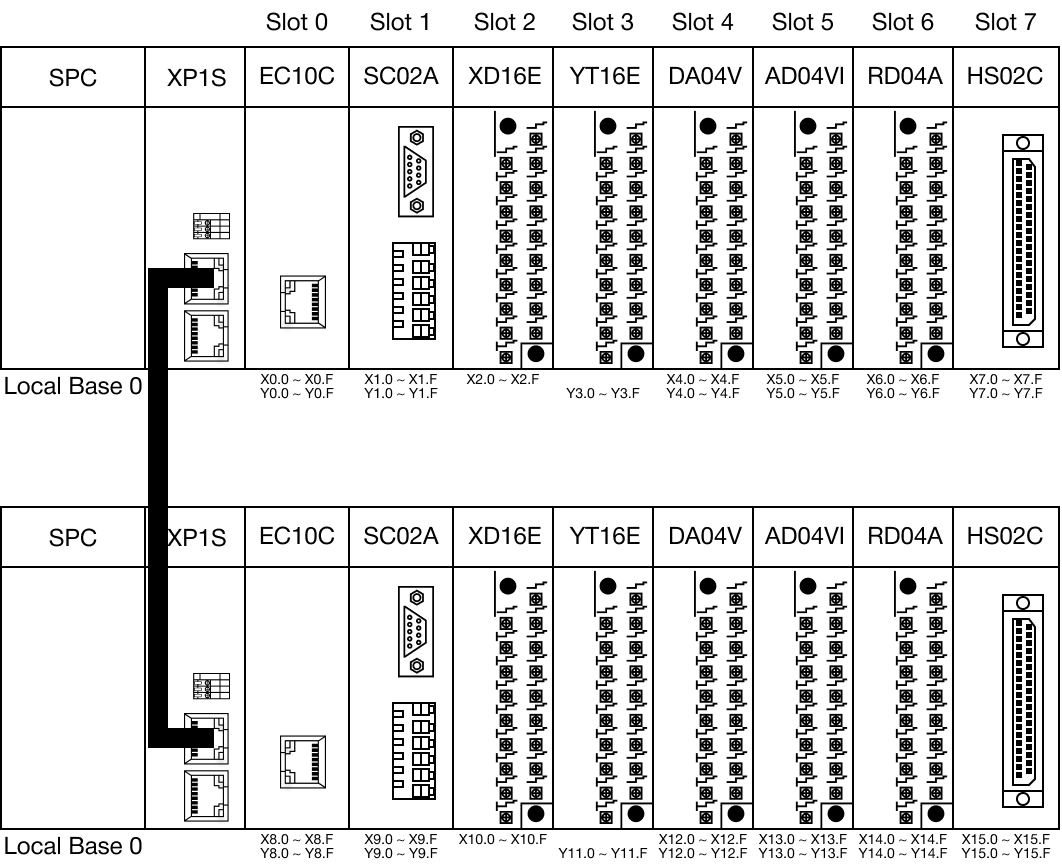
CM1 Series Configuration
Please refer to the below image for the Base and Slot Number for the CM1 series.
Execution Condition
It is recommended that the IOEXC instructions be used with a pulse contact as an execution condition, or use the IOEXCP instruction.
Instruction Behavior
The IOEXC and IOEXCP instructions behave as follows:
- The WORD data register S can be assigned BOOL values.
- Assign S 0 upon conclusion of replacing the I/O expansion module.
- Assign S 1 to signal I/O expansion module replacement is occurring.
- Both instructions are for I/O and special expansion modules that do NOT require module setups and special programs.
- Example: Analog modules.