Block Series Connection (AND)
Connection Requirements
Supported PLC Series
| XPnA/1R | XPnB | XPnE | XPnF | CP3A/B/P/U CP4A~D/U | CPnE | CPnF | BP | PLC-S |
|---|---|---|---|---|---|---|---|---|
| ✓ | ✓ | ✓ | ✓ | ✓ | ✓ | ✓ | ✓ | ✓ |
Supported Data Registers
| M | X | Y | K | L | F | T | C | S | Z | R | Q | D | @D | Constant |
|---|---|---|---|---|---|---|---|---|---|---|---|---|---|---|
| - | - | - | - | - | - | - | - | - | - | - | - | - | - | - |
Supported Flags
| Flag | Bit | Support |
|---|---|---|
| Error | F11.0 | - |
| Zero | F11.1 | - |
| Carry | F11.2 | - |
Number of Steps
| Steps |
|---|
| 1 |
Notice
Connection Behavior
The ANB block series connection behaves as follows:
- An AND operation is performed on block A and block B and uses the new result as a new execution condition.
- ANB is not a contact signal.
- ANB is a connection signal.
- In the Instruction List (IL) mode, ANB can be written consecutively up to 15 connections (16 blocks).
- If more ANB connections are written consecutively, the operation may not be performed properly.
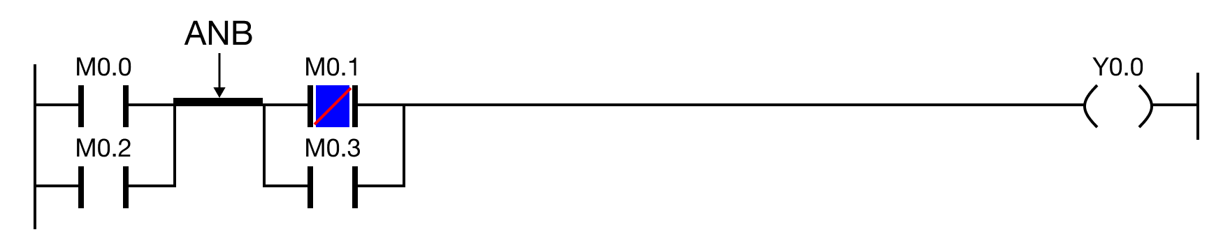
ANB refers to the bus bar connection between the two blocks horizontally.