Example - Ladder Diagram
PWM Example

The Pulse-Width modulation (PWM) instruction outputs pulses set by S2 for a set amount of time, S1, to the output module or data register, D2.
Ladder Diagram Example
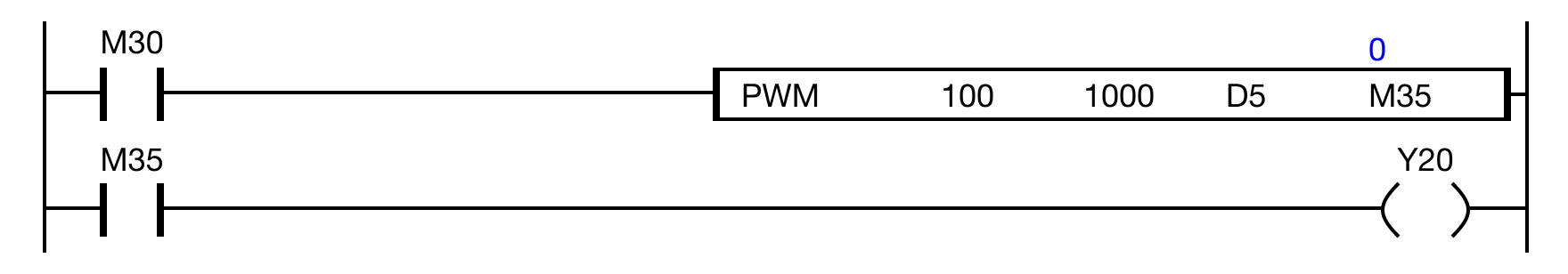
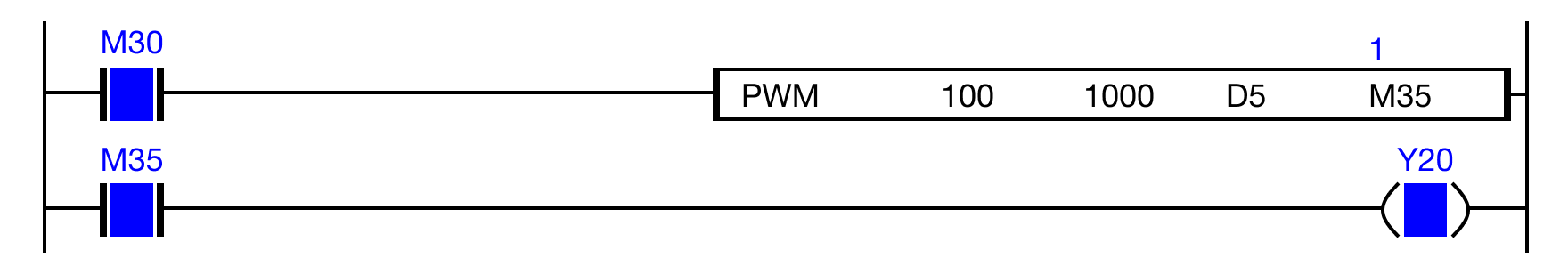
When the contact, M3.0, is ON (1), the PWM operation is outputting 1,000 pulses every 100ms.
When the PWM operation is ON (1), the output device, M3.5, receives the pulses.
When M3.5 receives pulses, the coil, Y2.0, is energized.
The coil, Y2.0, is energized with 1,000 pulses every 100ms.
Memory Monitor
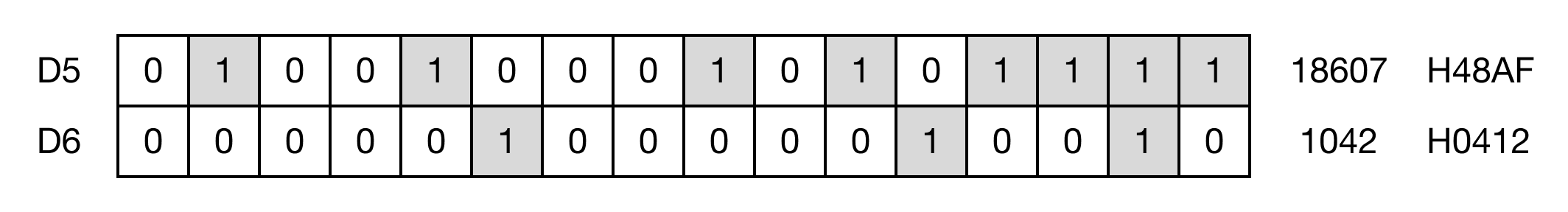
Binary result of the result value, D5, before the PWM operation.
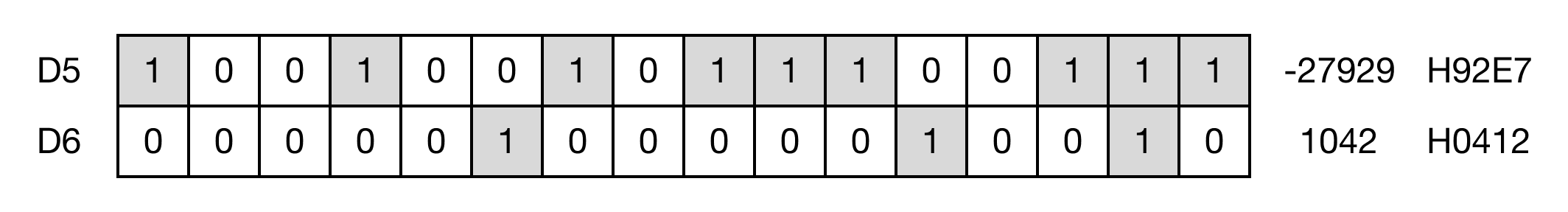
Binary result of the result value, D5, after the PWM operation.