Example - Ladder Diagram
DTO

The DTO instruction writes n3 number of DWORD data, S, to the buffer memory location, n2, on the expansion module, n1.
Ladder Diagram Example

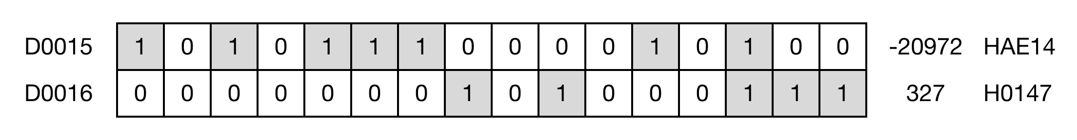
When the contact, M3.0, is ON (1), 2 DWORD values of the data register, D15, is written to buffer memory 22 on the expansion module at slot H0003.

In this example, 21,474,836 is written to the digital value range buffer memory of the CM3-SP04EAA expansion module at slot 3.
Memory Monitor
DTOP

The DTOP one-shot instruction writes n3 number of DWORD data, S, to the buffer memory location, n2, on the expansion module, n1.
Every time this instruction executes, it energizes the output only once.
Ladder Diagram Example

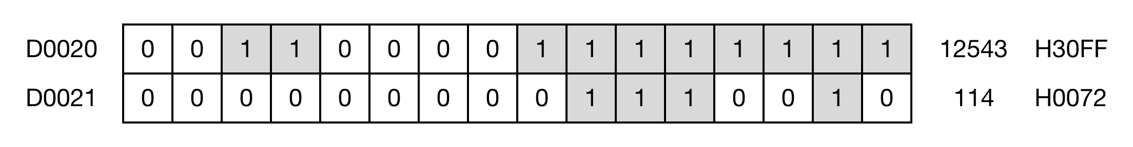
When the contact, M4.0, is ON (1), 1 DWORD value of the data register, D20, is written to buffer memory 52 on the expansion module at slot H0004.

In this example, 7,483,647 is written to the minimum temperature value buffer memory (channel 2) of the CM3-SP04ERO expansion module at slot 4.
Memory Monitor