Example - Ladder Diagram
DATEWR

The DATEWR instruction writes the WORD data from the data register S to a real time clock (RTC) device.
Ladder Diagram Example
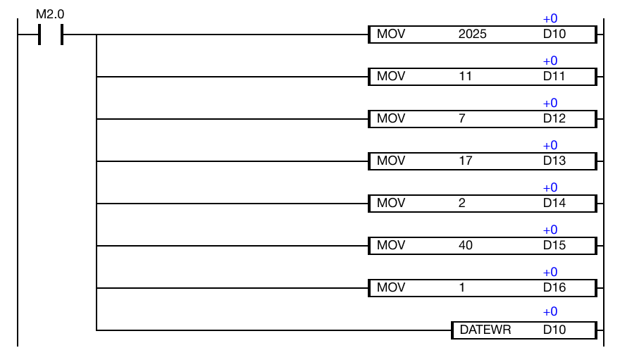
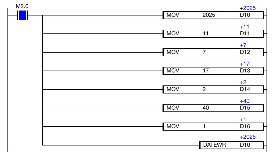
When the contact, M2.0, is powered ON (1), the instruction writes the block of time data, starting at the data register, D10, to the real time clock (RTC) device.
Memory Monitor
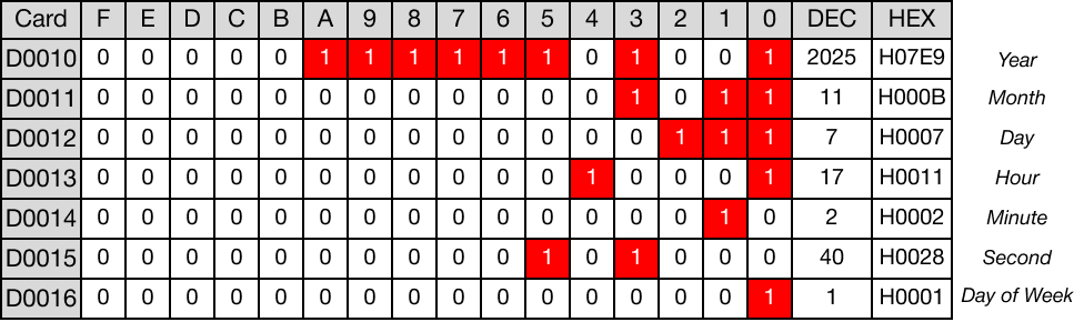
- The following data is written to the real time clock device:
- D10: 2025 (Year)
- D11: 11 (Month, November)
- D12: 7 (Day)
- D13: 17 (Hour)
- D14: 2 (Minute)
- D15: 40 (Second)
- D16: 1 (Day of the week, Monday)
The clock time is set to: 5:02:40 P.M., Monday, November 7, 2025.
DATEWRP

The DATEWRP one-shot instruction writes the WORD data from the data register S to a real time clock (RTC) device.
Every time this instruction executes, it energizes the output only once.
Ladder Diagram Example
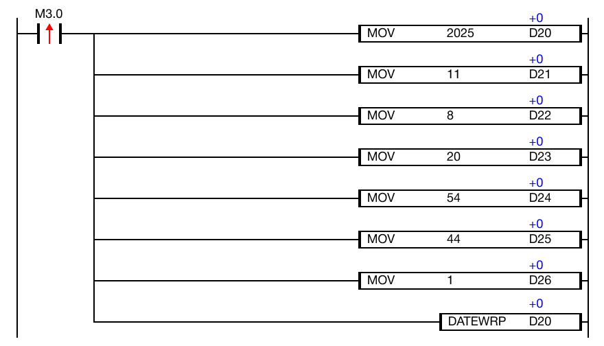
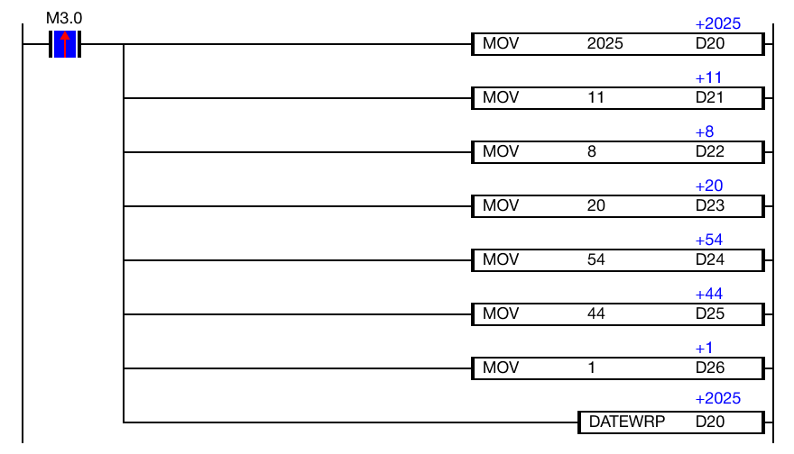
When the contact, M3.0, is powered ON (1), the instruction writes the block of time data, starting at the data register, D20, to the real time clock (RTC) device.
Memory Monitor
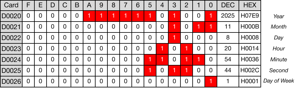
- The following data is written to the real time clock device:
- D20: 2025 (Year)
- D21: 11 (Month, November)
- D22: 8 (Day)
- D23: 20 (Hour)
- D24: 54 (Minute)
- D25: 44 (Second)
- D26: 1 (Day of the week, Monday)
The clock time is set to: 8:54:44 P.M., Monday, November 8, 2025.