Example - Ladder Diagram
BK<
The BK< instruction compares n number of WORD data registers starting at S1 to n number of WORD data registers starting at S2.
For each data register in the range S1 ~ Sn that is less than each data register in the range S2 ~ Sn, the corresponding bit in the data register D, starting at bit number B, will turn ON (1).
Ladder Diagram Example

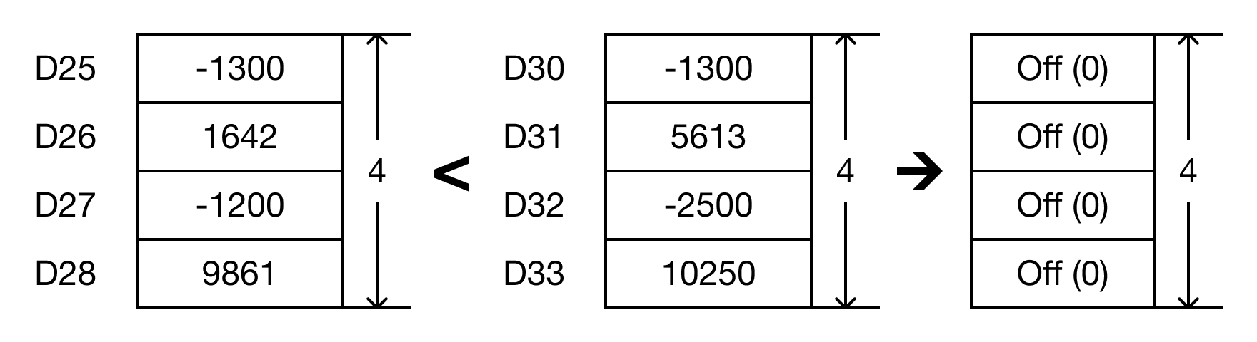
- The BK< instruction will compare the following expressions for a true or false value:
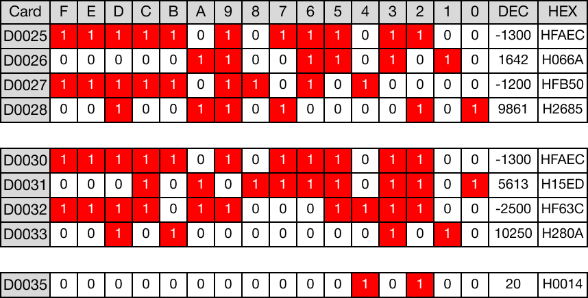
- D25 < D30 → -1,300 < -1,300
- D26 < D31 → 1,642 < 5,613
- D27 < D32 → -1,200 < -2,500
- D28 < D33 → 9,861 < 10,250

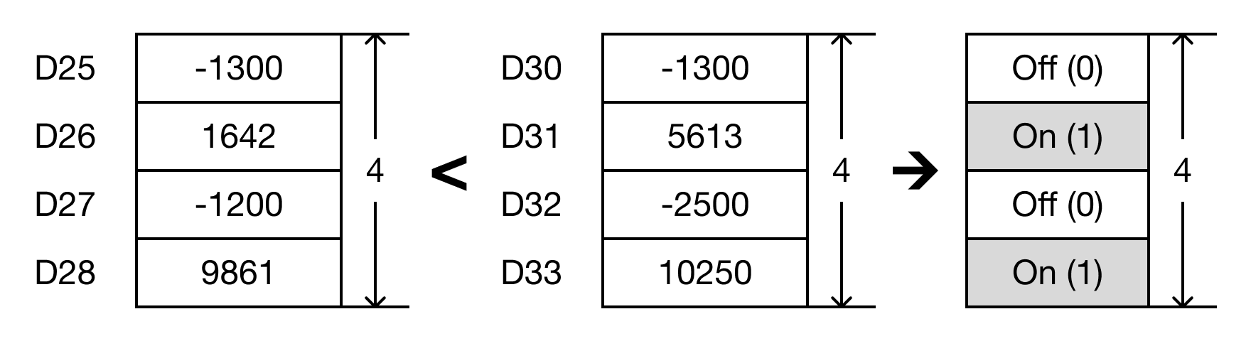
- When the open contact, M0.0, is powered ON (1), the values of the data registers are compared.
- D25 < D30 → -1,300 < -1,300 (FALSE → D35.1 = 0)
- D26 < D31 → 1,642 < 5,613 (TRUE → D35.2 = 1)
- D27 < D32 → -1,200 < -2,500 (FALSE → D35.3 = 0)
- D28 < D33 → 9,861 < 10,250 (TRUE → D35.4 = 1)
Memory Monitor
BK<P
The BK<P one-shot instruction compares n number of WORD data registers starting at S1 to n number of WORD data registers starting at S2.
For each data register in the range S1 ~ Sn that is less than each data register in the range S2 ~ Sn, the corresponding bit in the data register D, starting at bit number B, will turn ON (1).
Every time this instruction executes, it energizes the output only once.
Ladder Diagram Example

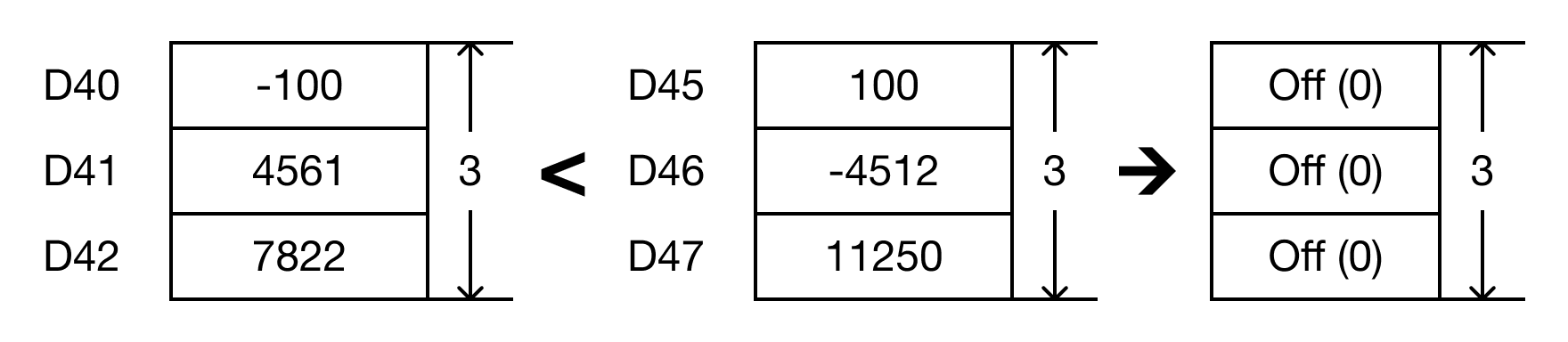
- The BK<P instruction will compare the following expressions for a true or false value:
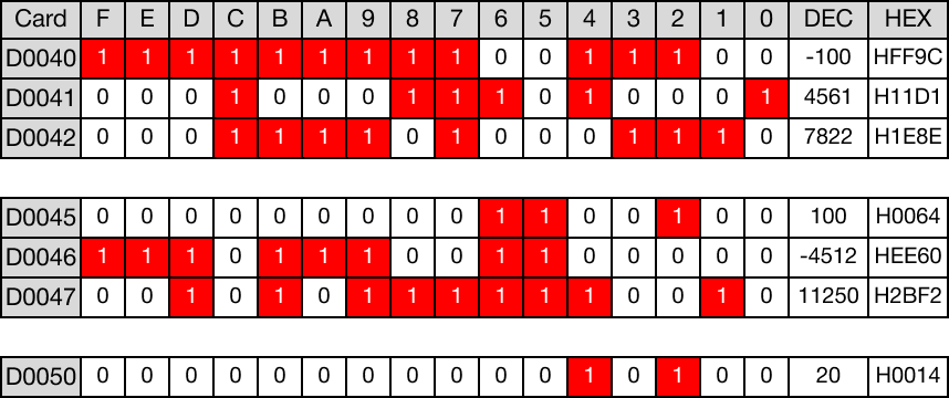
- D40 < D45 → -100 < 100
- D41 < D46 → 4,561 < -4,512
- D42 < D47 → 7,822 < 11,250


- When the open contact, M0.1, is powered ON (1), the values of the data registers are compared.
- D40 < D45 → -100 < 100 (TRUE → D50.2 = 1)
- D41 < D46 → 4,561 < -4,512 (FALSE → D50.3 = 0)
- D42 < D47 → 7,822 < 11,250 (TRUE → D50.4 = 1)
Memory Monitor