Example - Ladder Diagram
CTD

The CTD instruction starts from the value v, and counts down to 0. The count number is saved in a counter data register, CC. If the value of CC is equal to 0, the counter contact, C, energizes.
Ladder Diagram Example

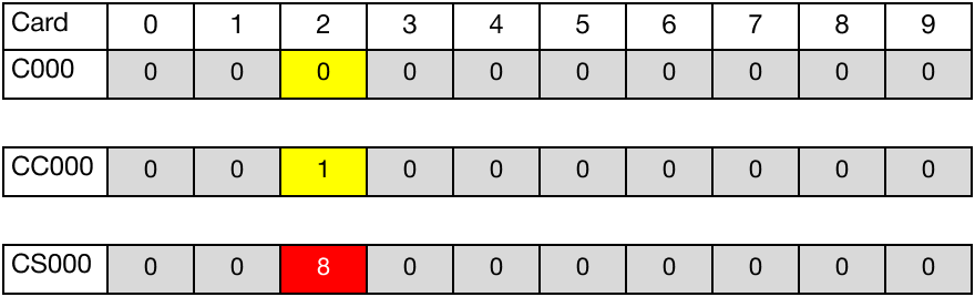
The initial value of the BOOL counter data register, C0.0, is 0.
The initial value of the WORD current count data register, CC0.0, is 8.
The initial value of the WORD set count data register, CS0.0, is 8.

When the contact, M1.0, is powered ON (1), the counter instruction counts down by 1, decreasing the current count data register, CC0.0, to 7.


When the contact, M1.0, is powered ON (1) again, the counter instruction counts down by 1, decreasing the current count data register, CC0.0, to 1.

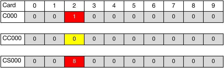
When the contact, M1.0, is powered ON (1) again, the counter instruction counts down by 1, decreasing the current count data register, CC0.0, to 0.

Since CC0.0 is equal to CS0.0, the BOOL counter data register, C0.0, is set to 1.
As a result, the coil, Y0.2, is energized.
When the contact, M1.1, is powered ON (1), the value the current count data register, CC0.0, resets to 8.
Since CC0.00 is greater than CS10, the BOOL counter data register, C0.0, is set to 0.
As a result, the coil, Y0.2, is deenergized.
