Example - Ladder Diagram
FIFW

The FIFW instruction writes the WORD value from the data register, DEV, into the table, TBL, starting at an offset of 1 (TBL + 1).
Ladder Diagram Example


When the contact, M1.0, is powered ON (1), the FIFW instruction writes 1 to the data register, D2.
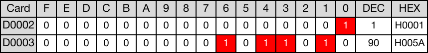
As a result, 90 is written to the data register, D3 (D2 + 1).

When the FIFW instruction is executed again, the data register, D2, increases its count by one to 2.
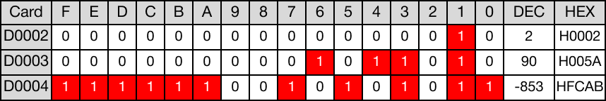
As a result, -853 is written to the data register, D4 (D2 + 2).

When the FIFW instruction is executed again, the data register, D2, increases its count by one to 3.
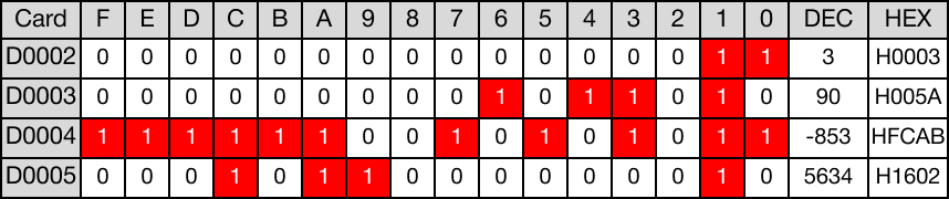
As a result, 5,634 is written to the data register, D5 (D2 + 3).

When the FIFW instruction is executed again, the data register, D2, increases its count by one to 4.
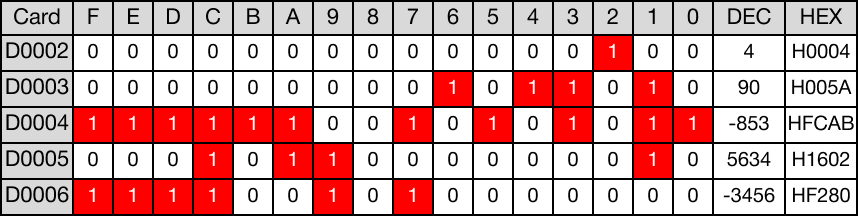
As a result, -3,456 is written to the data register, D6 (D2 + 4).
FIFWP

The FIFWP one-shot instruction writes the WORD value from the data register, DEV, into the table, TBL, starting at an offset of 1 (TBL + 1).
Every time this instruction executes, it energizes the output only once.
Ladder Diagram Example


When the contact, M1.1, is powered ON (1), the FIFWP instruction writes 1 to the data register, D7.
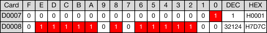
As a result, 32,124 is written to the data register, D8 (D7 + 1).

When the FIFWP instruction is executed again, the data register, D7, increases its count by one to 2.
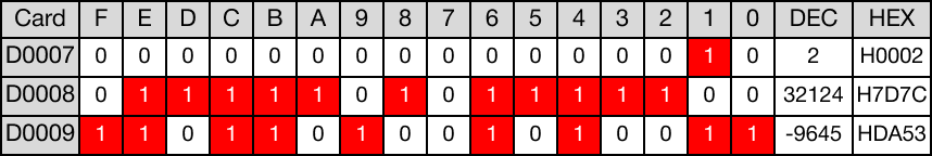
As a result, -9,645 is written to the data register, D9 (D7 + 2).

When the FIFWP instruction is executed again, the data register, D7, increases its count by one to 3.
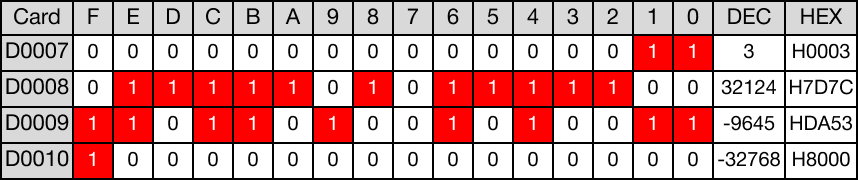
As a result, -32,768 is written to the data register, D10 (D7 + 3).