Example - Ladder Diagram
BKAND

The BKAND instruction performs a logical AND on n number of WORD data registers starting at S1 and n number of data registers starting at S2 and saves the result in an assigned WORD data register, D.
Ladder Diagram Example

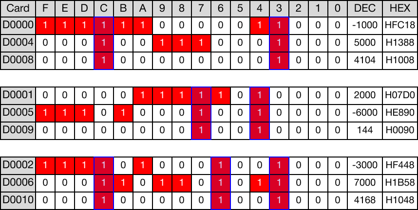
When the contact, M6.0, is powered ON (1), logical AND operations are performed on 3 WORD data registers, D0, D1, and D2, with another 3 WORD data registers, D4, D5, and D6.
The results of the logical AND operations are saved in 3 WORD data registers, D8, D9, and D10.

Memory Monitor
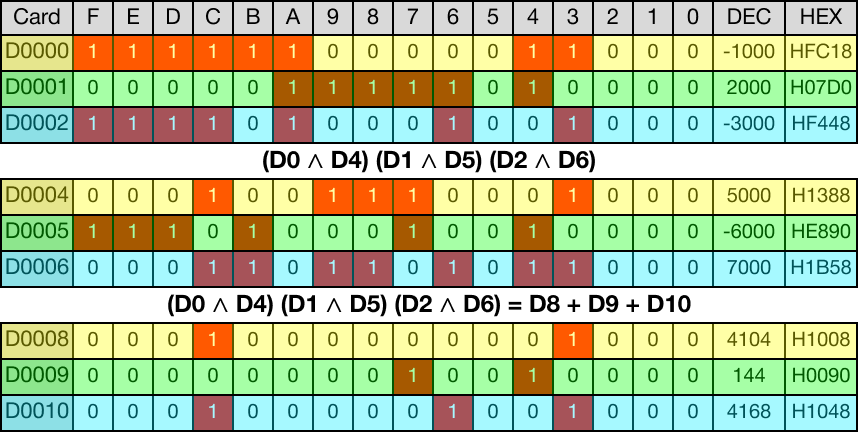
The below image shows the direct logical AND operations for each data register.
BKANDP

The BKANDP one-shot instruction performs a logical AND on n number of WORD data registers starting at S1 and n number of data registers starting at S2 and saves the result in an assigned WORD data register, D.
Every time this instruction energizes, it executes only once.
Ladder Diagram Example

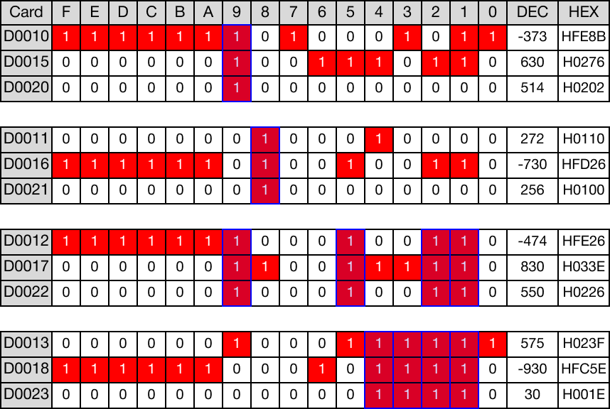
When the contact, M7.0, is powered ON (1), logical AND operations are performed on 4 WORD data registers, D10, D11, D12, and D13, with another 4 WORD data registers, D15, D16, D17, and D18.
The results of the logical AND operations are saved in 4 WORD data registers, D20, D21, D22, and D23.

Memory Monitor
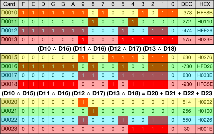
The below image shows the direct logical AND operations for each data register.