Example - Ladder Diagram
DAND

The DAND instruction performs a logical AND on the DWORD value, S1, and the DWORD value, S2, and saves the result in an assigned DWORD data register, D.
Ladder Diagram Example

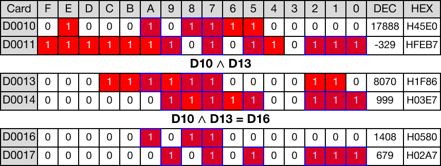
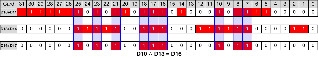
When the contact, M2.0, is powered ON (1), a logical AND operation is performed on the DWORD data registers, D10 and D13.
The result of the logical AND operation is saved in the DWORD data register, D16.

Memory Monitor
DANDP

The DANDP one-shot instruction performs a logical AND on the DWORD value, S1, and the DWORD value, S2, and saves the result in an assigned DWORD data register, D.
Every time this instruction energizes, it executes only once.
Ladder Diagram Example

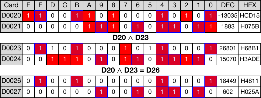
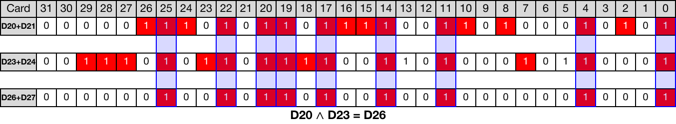
When the contact, M3.0, is powered ON (1), a logical AND operation is performed on the DWORD data registers, D20 and D23.
The result of the logical AND operation is saved in the DWORD data register, D26.

Memory Monitor