Example - Ladder Diagram
BKXNR

The BKXNR instruction performs a logical XNOR on n number of WORD data registers starting at S1 and n number of data registers starting at S2 and saves the result in an assigned WORD data register, D.
Ladder Diagram Example

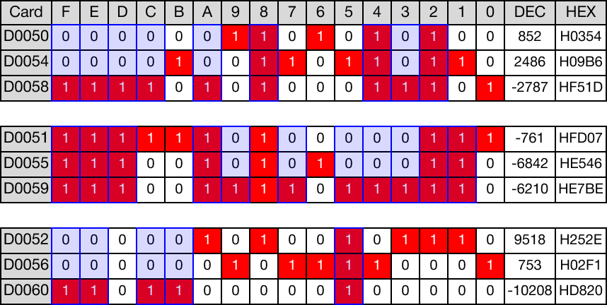
When the contact, M1.5, is powered ON (1), logical XNOR operations are performed on 3 WORD data registers, D50, D51, and D52, with another 3 WORD data registers, D54, D55, and D56.
The results of the logical XNOR operations are saved in 3 WORD data registers, D58, D59, and D60.

Memory Monitor
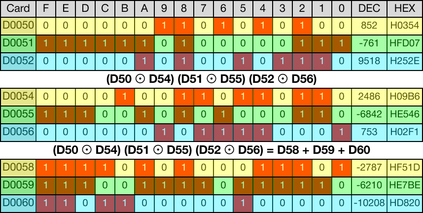
The below image shows the direct logical XNOR operations for each data register.
BKXNRP

The BKXNRP one-shot instruction performs a logical XNOR on n number of WORD data registers starting at S1 and n number of data registers starting at S2 and saves the result in an assigned WORD data register, D.
Every time this instruction energizes, it executes only once.
Ladder Diagram Example

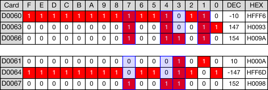
When the contact, M1.7, is powered ON (1), logical XNOR operations are performed on 2 WORD data registers, D60, and D61, with another 2 WORD data registers, D63, and D64.
The results of the logical XNOR operations are saved in 2 WORD data registers, D66, and D67.

Memory Monitor
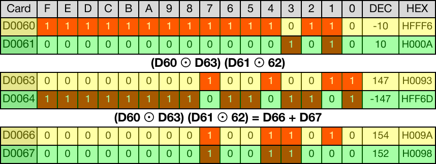
The below image shows the direct logical XNOR operations for each data register.