Example - Ladder Diagram
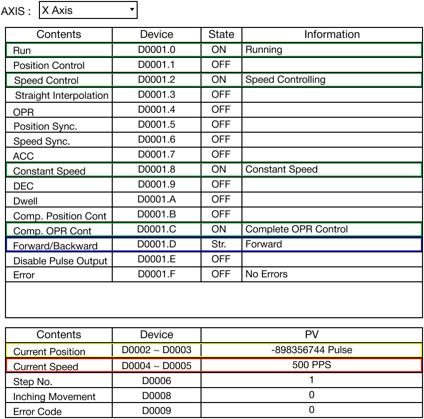
PSTRT1

The PSTRT1 instruction controls the motion of the X-axis on the positioning module, Base/Slot. The control data, S, defines the control motion of the X-axis and saves the operation status in the assigned WORD data register, D.
Ladder Diagram Example

When the contact, M0.0, is powered ON (1), the PSTRT1 instruction controls the X-axis' motion.
The operation result is saved in the data register, D30.

Memory Monitor

Program Monitor
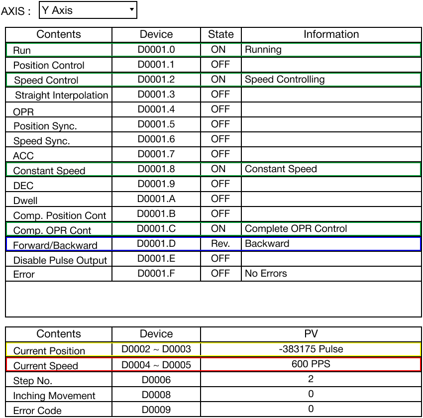
PSTRT2

The PSTRT2 instruction controls the motion of the Y-axis on the positioning module, Base/Slot. The control data, S, defines the control motion of the Y-axis and saves the operation status in the assigned WORD data register, D.
Ladder Diagram Example

When the contact, M0.0, is powered ON (1), the PSTRT2 instruction controls the Y-axis' motion.
The operation result is saved in the data register, D40.

Memory Monitor

Program Monitor