Example - Ladder Diagram
DRCR

The DRCR instruction will rotate the DWORD value, D, n number of bits to the right. The result of the rotation is saved in the same assigned DWORD data register, D.
The carry flag, F11.2, can be used.
Ladder Diagram Example

The initial value of the DWORD data register, D30, is 23,204,308.
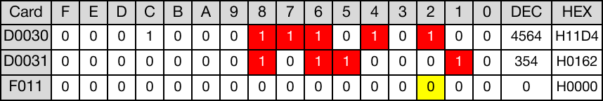
When the contact, M6.0, is powered ON (1), the DWORD data register, D30, rotates 2 bits to the right.

The value of the DWORD data register, D30, changes from 23,204,308 to 5,801,077.
After rotation, no overflow occurred. The value of the carry flag bit, F11.2, is 0.

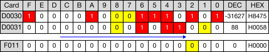
When the instruction is reenergized, the value of the DWORD data register, D30, changes from 5,801,077 to -2,146,033,379.
After rotation, no overflow occurred. The value of the carry flag bit, F11.2, is 0.
DRCRP

The DRCRP one-shot instruction will rotate the DWORD value, D, n number of bits to the right. The result of the rotation is saved in the same assigned DWORD data register, D.
The carry flag, F11.2, can be used.
Every time this instruction executes, it energizes the output only once.
Ladder Diagram Example

The initial value of the DWORD data register, D40, is 1,331,818,798.
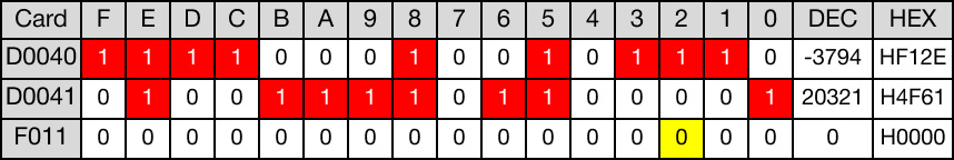
When the contact, M7.0, is powered ON (1), the DWORD data register, D40, rotates 3 bits to the right.

The value of the DWORD data register, D40, changes from 1,331,818,798 to -1,981,006,299.
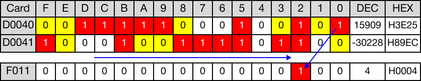
After rotation, overflow occurred.
The value of the carry flag bit, F11.2, is 1, which is part of the data from the WORD data register, D40.

When the instruction is reenergized, the value of the DWORD data register, D40, changes from -1,981,006,299 to 1,899,857,860.
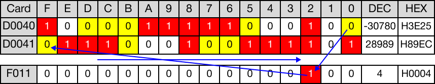
After rotation, overflow occurred.
The value of the carry flag bit, F11.2, is 1, which is part of the data from the DWORD data register, D40.