Example - Ladder Diagram
DROR

The DROR instruction will rotate the DWORD value, D, n number of bits to the right. The result of the rotation is saved in the same assigned DWORD data register, D.
Ladder Diagram Example

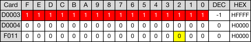
The initial value of the DWORD data register, D1, is 503,513,141.
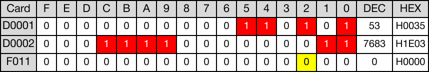
When the contact, M2.0, is powered ON (1), the DWORD data register, D1, rotates 2 bits to the right.

The value of the DWORD data register, D1, changes from 503,513,141 to 1,199,620,109.
After rotation, overflow occurred. The value of the carry flag bit, F11.2, is 1.

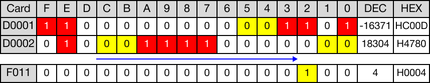
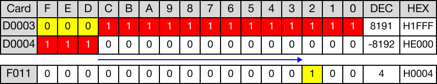
When the instruction is reenergized, the value of the DWORD data register, D1, changes from 1,199,620,109 to 1,373,646,851.
After rotation, no overflow occurred. The value of the carry flag bit, F11.2, is 0.

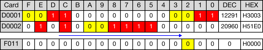
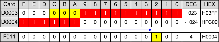
When the instruction is reenergized, the value of the DWORD data register, D1, changes from 1,373,646,851 to -730,330,112.
After rotation, overflow occurred. The value of the carry flag bit, F11.2, is 1.
DRORP

The DRORP one-shot instruction will rotate the DWORD value, D, n number of bits to the right. The result of the rotation is saved in the same assigned DWORD data register, D.
Every time this instruction executes, it energizes the output only once.
Ladder Diagram Example

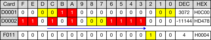
The initial value of the DWORD data register, D3, is 65,535.
When the contact, M3.0, is powered ON (1), the DWORD data register, D3, rotates 3 bits to the right.

The value of the DWORD data register, D3, changes from 65,535 to -536,862,721.
After rotation, overflow occurred. The value of the carry flag bit, F11.2, is 1.

When the instruction is reenergized, the value of the DWORD data register, D3, changes from -536,862,721 to -67,107,841.
After rotation, overflow occurred. The value of the carry flag bit, F11.2, is 1.