Example - Ladder Diagram
BSFL

The BSFL instruction shifts n-bit data of the data register, D, 1 bit to the left starting at the bit, D.
The carry flag, F11.2, can be used.
Ladder Diagram Example

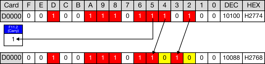
The initial value of the WORD data register, D4, is 10,100.
The initial value of the BOOL data register, D4.2 is 1.

When the contact, M2.0, is powered ON (1), the instructions shifts 5 bits of the WORD data register, D4, 1 bit to the left, starting at the BOOL data register, D4.2.

The value of the WORD data register, D4, changes from 10,100 to 10,088.
The value of the BOOL data register, D4.2 changes from 1 to 0.
The existing bits are shifted 1 bit to the left. The most significant bit is shifted into the carry flag bit, F11.2.
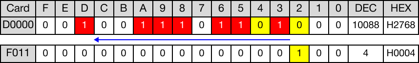
When the instruction is reenergized, the bits are shifted 1 bit to the left again.
The value of the WORD data register, D4, changes from 10,088 to 10,064.
The value of the BOOL data register, D4.2 remains 0.
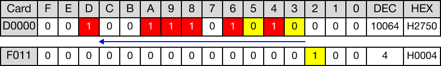
The existing bits are shifted 1 bit to the left. The most significant bit is shifted into the carry flag bit, F11.2.
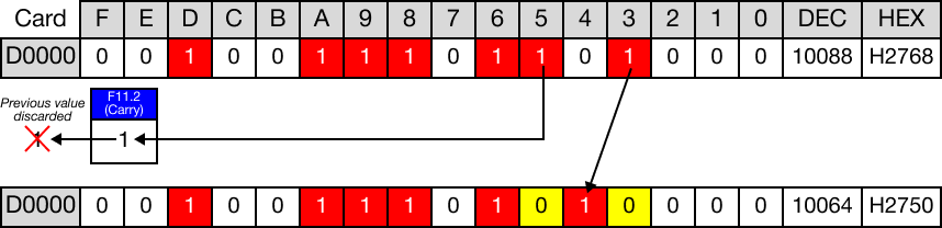
The previous value stored in the carry flag bit, F11.2, is discarded.
BSFLP

The BSFLP one-shot instruction shifts n-bit data of the data register, D, 1 bit to the left starting at the bit, D.
The carry flag, F11.2, can be used.
Every time this instruction executes, it energizes the output only once.
Ladder Diagram Example

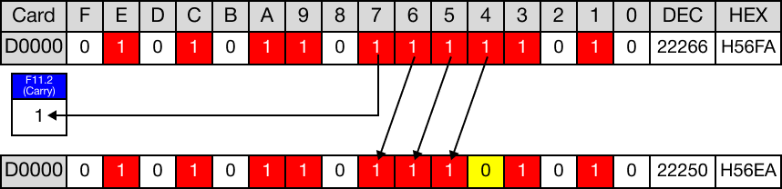
The initial value of the WORD data register, D5, is 22,266.
The initial value of the BOOL data register, D5.4 is 1.
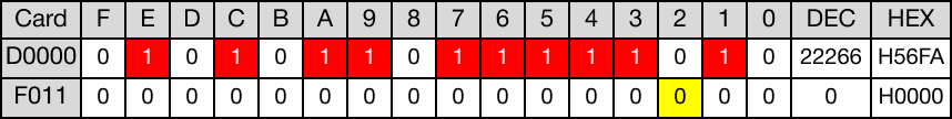
When the contact, M2.1, is powered ON (1), the instructions shifts 4 bits of the WORD data register, D5, 1 bit to the left, starting at the BOOL data register, D5.4.

The value of the WORD data register, D5, changes from 22,266 to 22,250.
The value of the BOOL data register, D5.4 changes from 1 to 0.
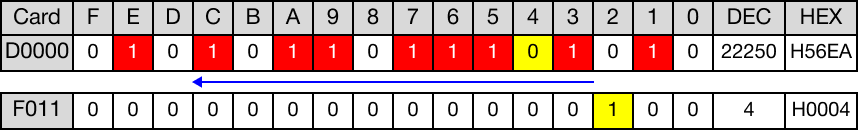
The existing bits are shifted 1 bit to the left. The most significant bit is shifted into the carry flag bit, F11.2.