Example - Ladder Diagram
SFL

The SFL instruction will shift the WORD value, D, n number of bits to the left. The result of the rotation is saved in the same assigned WORD data register, D.
The carry flag, F11.2, can be used.
Ladder Diagram Example

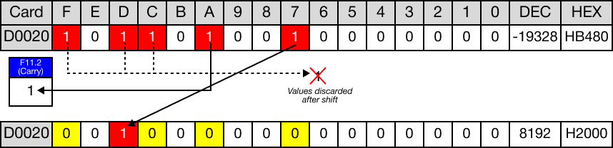
The initial value of the WORD data register, D20, is 2,770.
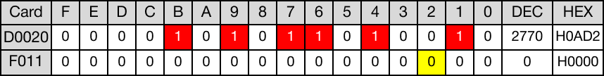
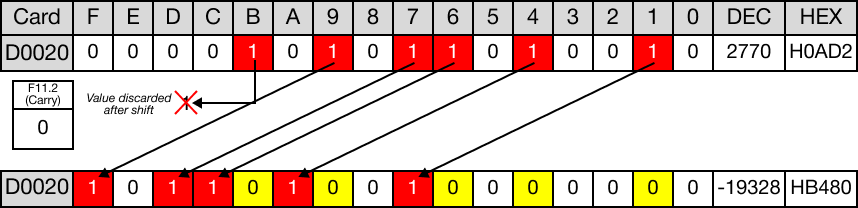
When the contact, M1.5, is powered ON (1), the instruction shifts the WORD data register, D20, 6 bits to the left.

The value of the WORD data register, D20, changes from 2,770 to -19,328.
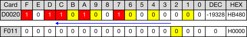
The bit shifted past bit F is discarded.
When the instruction is reenergized, the WORD data register, D20, is shifted 6 bits to the left again.

The value of the WORD data register, D20, changes from -19,328 to 8,192.
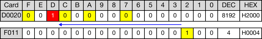
The bits shifted past bit F are discarded.
The last bit is shifted into the carry flag bit, F11.2.
SFLP

The SFLP one-shot instruction will shift the WORD value, D, n number of bits to the left. The result of the rotation is saved in the same assigned WORD data register, D
The carry flag, F11.2, can be used.
Every time this instruction executes, it energizes the output only once.
Ladder Diagram Example

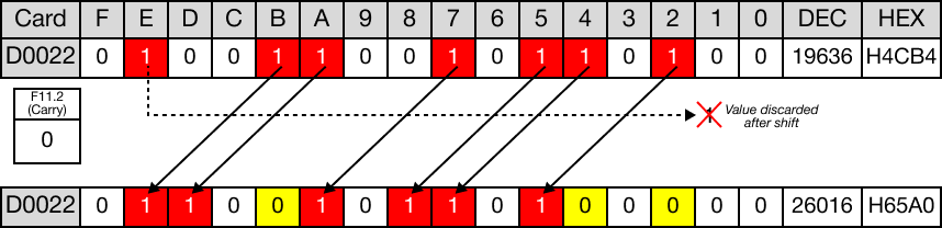
The initial value of the WORD data register, D22, is 19,636.
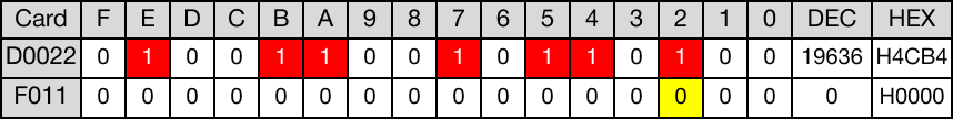
When the contact, M1.7, is powered ON (1), the instruction shifts the WORD data register, D22, 3 bits to the left.

The value of the WORD data register, D22, changes from 19,636 to 26,016.
The bit shifted past bit F is discarded.
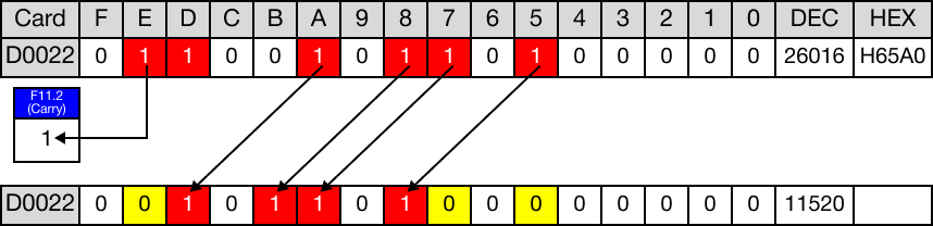
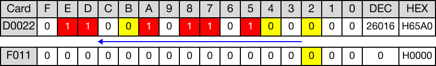
When the instruction is reenergized, the WORD data register, D22, is shifted 3 bits to the left again.

The value of the WORD data register, D22, changes from 26,016 to 11,520.
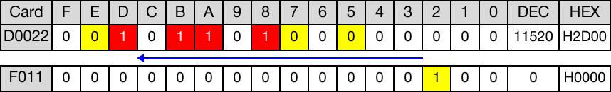
The last bit is shifted into the carry flag bit, F11.2.