Example - Ladder Diagram
SFR

The SFR instruction will shift the WORD value, D, n number of bits to the right. The result of the rotation is saved in the same assigned WORD data register, D.
The carry flag, F11.2, can be used.
Ladder Diagram Example

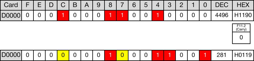
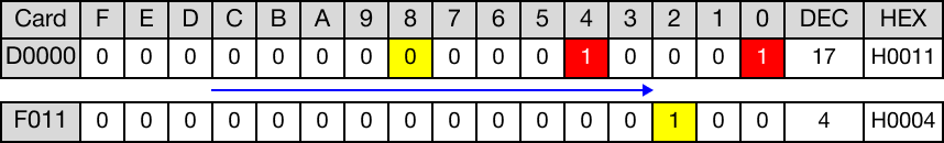
The initial value of the WORD data register, D0, is 4,496.
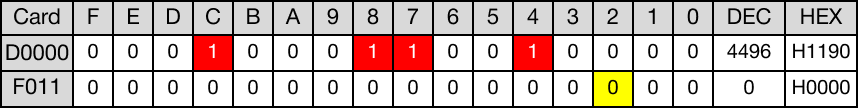
When the contact, M0.0, is powered ON (1), the instruction shifts the WORD data register, D0, 4 bits to the right.

The value of the WORD data register, D0, changes from 4,496 to 281.
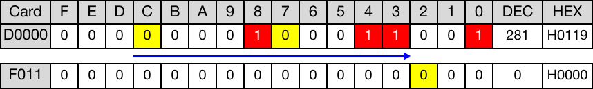
No bits shift past bit 0. So, no bits are discarded.
When the instruction is reenergized, the WORD data register, D0, is shifted 4 bits to the right again.

The value of the WORD data register, D0, changes from 281 to 17.
The bit shifted past bit 0 is discarded.
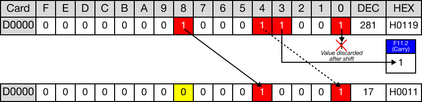
The last bit is shifted into the carry flag bit, F11.2.
SFRP

The SFRP one-shot instruction will shift the WORD value, D, n number of bits to the right. The result of the rotation is saved in the same assigned WORD data register, D
The carry flag, F11.2, can be used.
Every time this instruction executes, it energizes the output only once.
Ladder Diagram Example

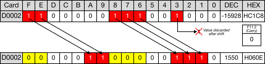
The initial value of the WORD data register, D2, is -15,928.
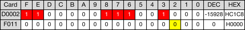
When the contact, M0.1, is powered ON (1), the instruction shifts the WORD data register, D2, 5 bits to the right.

The value of the WORD data register, D2, changes from -15,928 to 1,550.
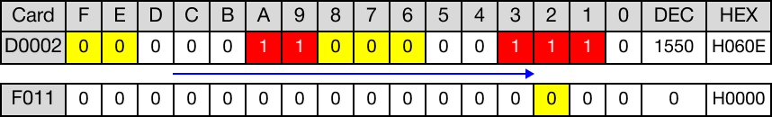
The bit shifted past bit 0 is discarded.
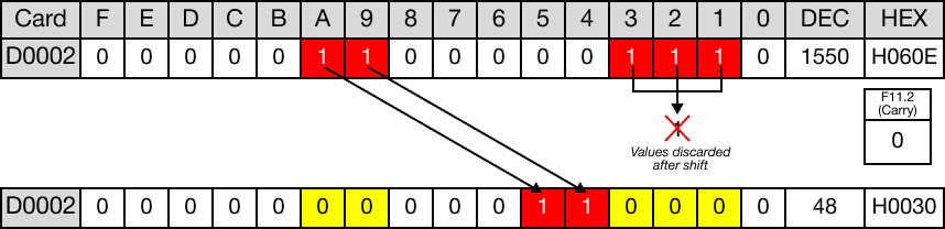
When the instruction is reenergized, the WORD data register, D2, is shifted 5 bits to the right again.

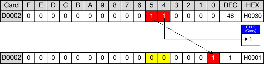
The value of the WORD data register, D2, changes from 1,550 to 48.
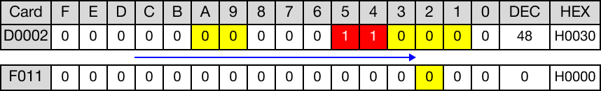
The bits shifted past bit 0 are discarded.
When the instruction is reenergized, the WORD data register, D2, is shifted 5 bits to the right again.

The value of the WORD data register, D2, changes from 48 to 1.
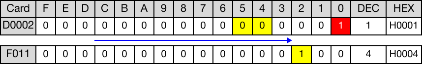
The last bit is shifted into the carry flag bit, F11.2.