Example - Ladder Diagram
TMR

The TMR instruction starts from a WORD value, v, and counts down to 0. The time is saved in a timer data register, t. If the instruction deenergizes, the value of TC is retained.
Ladder Diagram Example
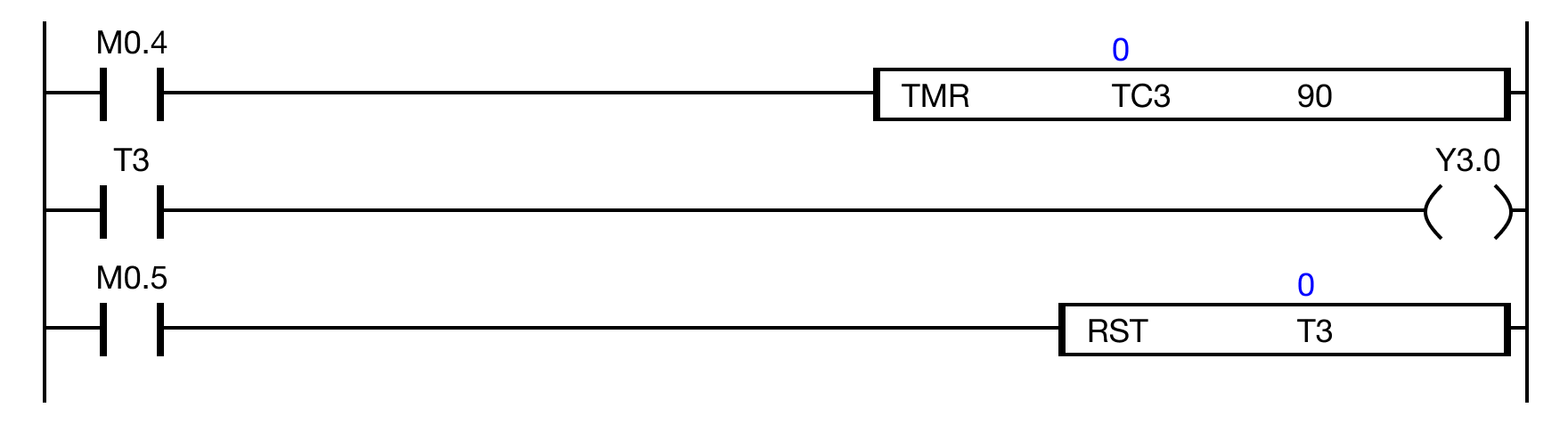
When the contact M0.4 is powered ON, the data register TC.3 counts up to 90.
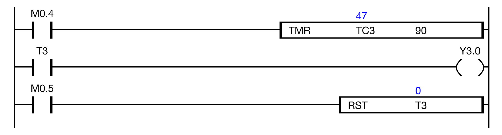
When the contact M0.4 is powered OFF, the data register TC.3 retains the current value.
In this case, 47.
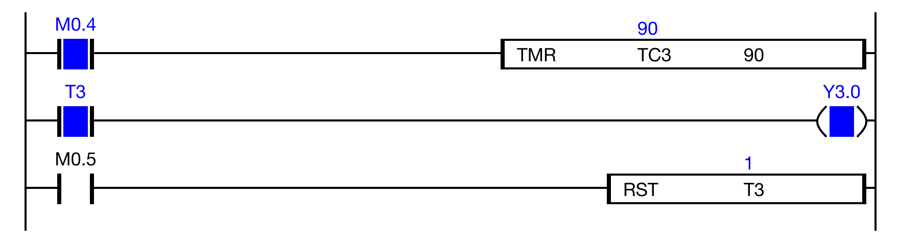
When the contact M0.4 is powered ON, the data register TC.3 continues counting to 90.
While the contact M0.4 is powered ON, the timer contact, T.3 is powered ON.
As a result, the coil Y3.0 is energized.
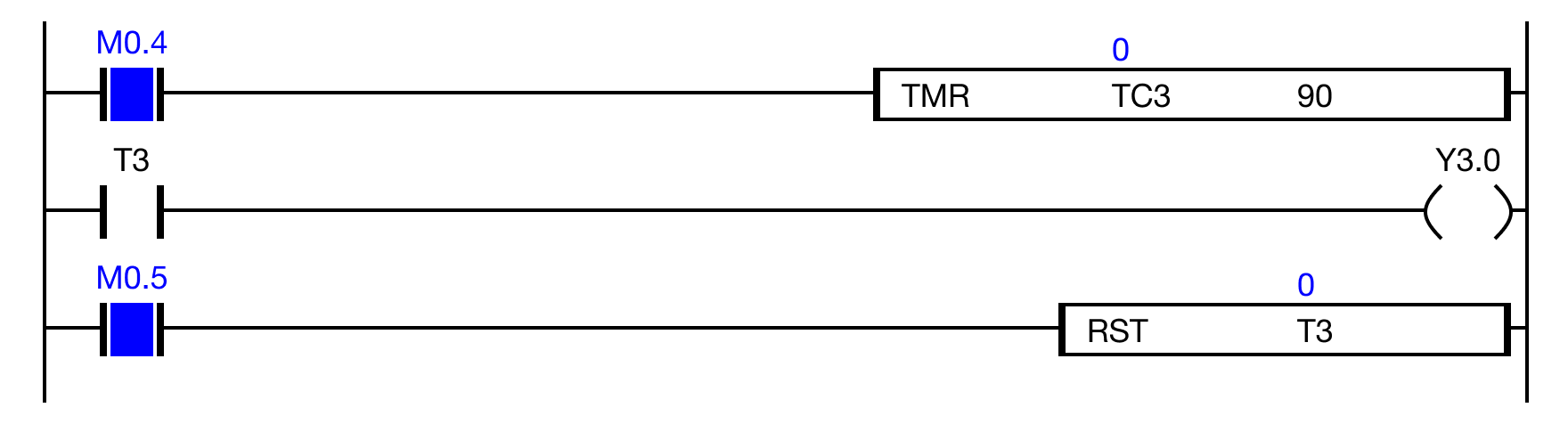
When the contact M0.5 is powered ON, the timer contact T.3 is reset.
The value of the data register TC.3 is reset to 0.
Memory Monitor
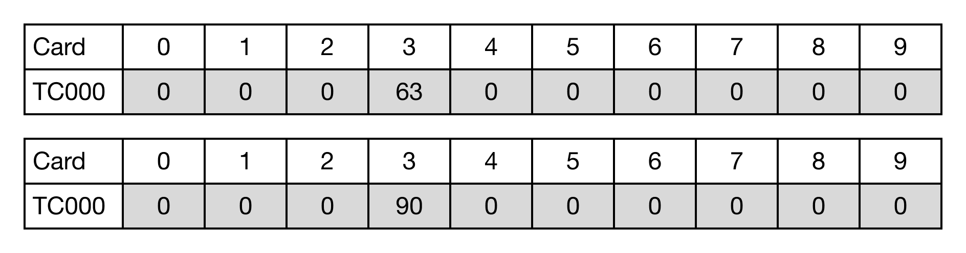
This is the result of the data register TC.3 counting up to 90 after the value 63 is retained.
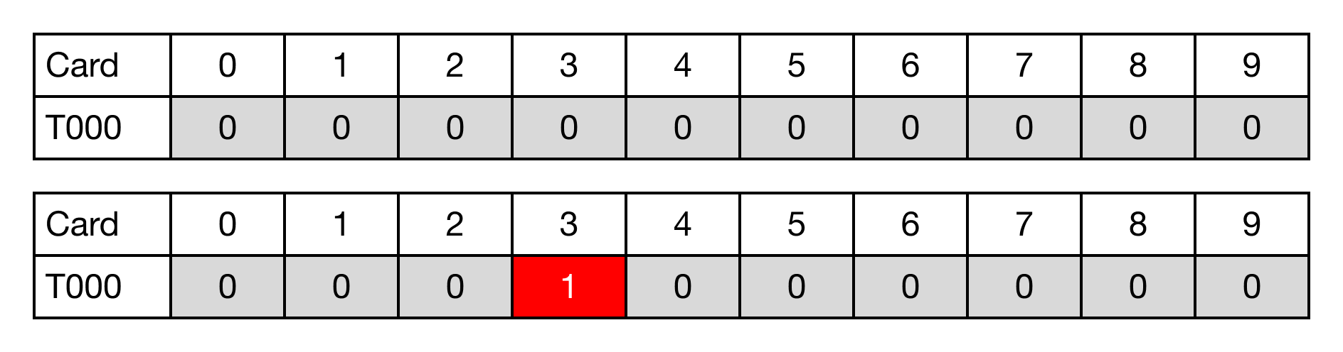
This is the result of the timer contact T.3 once the value of TC.3 is 90.