Example - Ladder Diagram
MCR

The MCR instruction declares the end of the Master Control area.
Ladder Diagram Example
Example 1
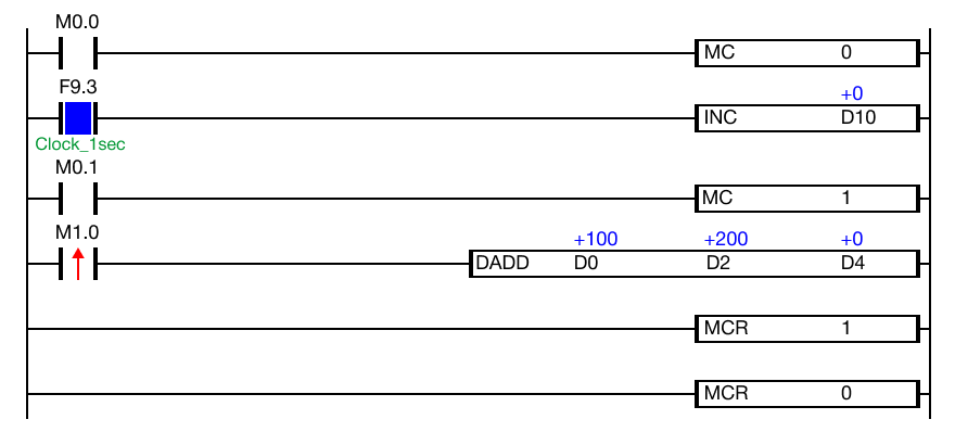
The Master Control area will execute the INC instruction every second if the contact, M0.0, is ON (1).
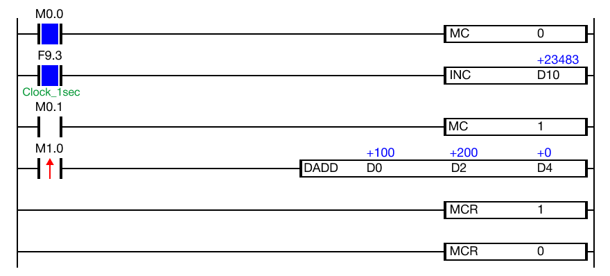
When the contact, M0.0, is powered ON (1), the INC instruction executes every second.
Every execution condition within MC 0 ~ MCR 0 will execute until M0.0 is OFF (0).
When the contact, M0.1, is OFF, MC 1 will NOT execute.
Even though the contact, M1.0 is powered ON (1), the DADD instruction will NOT execute.
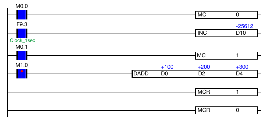
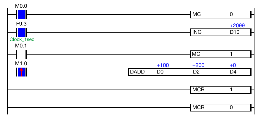
When the contact, M0.1, is powered ON (1), the DADD instruction will execute.
Every execution condition within MC 1 ~ MCR 1 will execute until M0.1 is OFF (0).
Example 2
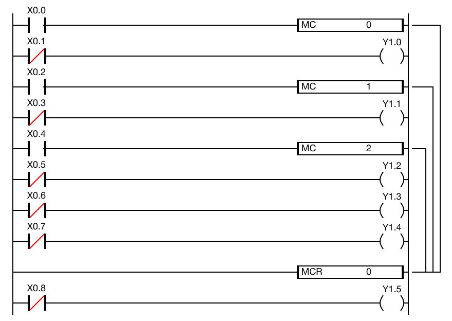
This example shows the lower to higher nesting order for the MC instruction where the MCR instruction terminates with the lowest possible value, 0.