Example - Ladder Diagram
CALL

The CALL instruction calls a subroutine program ID, n, in the same program.
Ladder Diagram Example
Example 1

When the contact, M0.0, is powered OFF (0), the CALL instruction is NOT calling the SBRT instruction.
As a result, the data register, D0, is NOT increasing every 1 scan by the INCP instruction.

When the contact, M0.0, is powered ON (1), the CALL instruction is calling the SBRT instruction.
As a result, the data register, D0, is increasing every 1 scan by the INCP instruction.
Example 2
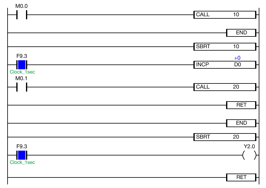
When the contact, M0.0, is powered OFF (0), the CALL instruction is NOT calling the SBRT instruction.
As a result, the data register, D0, is NOT increasing every 1 scan by the INCP instruction.
Additionally, the coil, Y2.0, is deenergized since the subroutine program with the ID 20 is not being called.
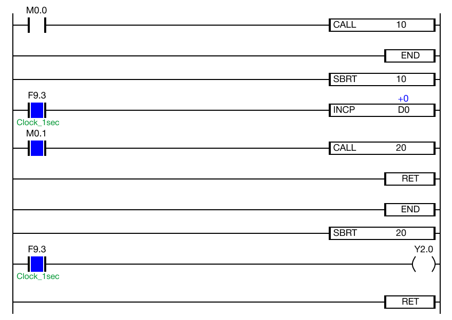
When the contact, M0.0 is powered OFF (0) and the contact, M0.1, is powered ON (1), the coil, Y2.0, remains deenergized.
This is because the subroutine program with the ID 20 is not being called.
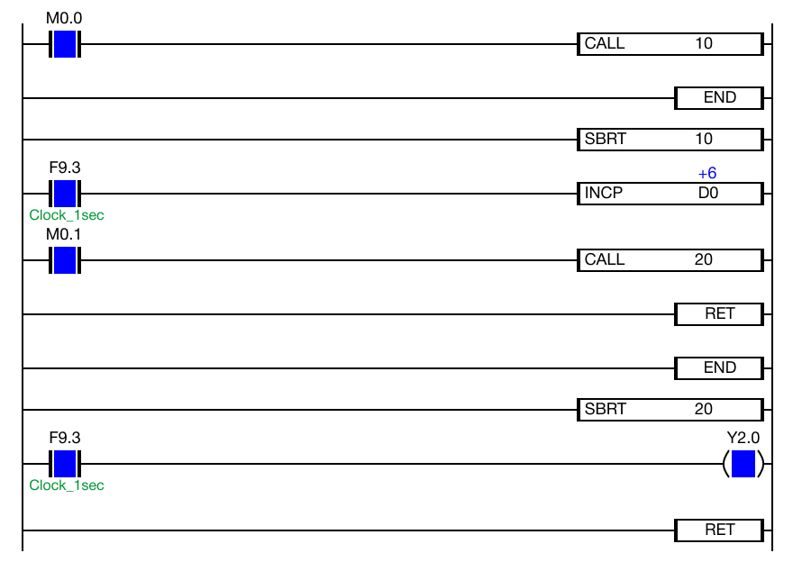
When the contacts, M0.0 and M0.1, are powered ON (1), the data register, D0, is increasing every 1 scan by the INCP instruction and the data register, Y2.0, is energizing every 1 second.
Both subroutines are being called allowing both poritons of the ladder logic to execute.
CALLP

The CALLP one-shot instruction calls a subroutine program ID, n, in the same program.
Every time this instruction executes, it energizes the output only once.
Ladder Diagram Example
Example 1

When the contact, M0.0, is powered OFF (0), the one-shot CALLP instruction is NOT calling the SBRT instruction.
As a result, the data register, D0, is NOT increasing every 1 scan by the INCP instruction.

When the contact, M0.0, is powered ON (1), the one-shot CALLP instruction is calling the SBRT instruction once every scan.
As a result, the data register, D0, is increasing every 1 scan by the INCP instruction.
Example 2

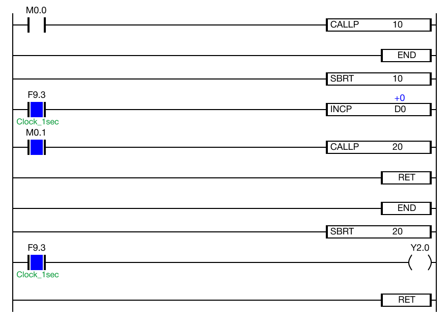
When the contact, M0.0, is powered OFF (0), the one-shot CALLP instruction is NOT calling the SBRT instruction.
As a result, the data register, D0, is NOT increasing every 1 scan by the INCP instruction.
Additionally, the coil, Y2.0, is deenergized since the subroutine program with the ID 20 is not being called.
When the contact, M0.0 is powered OFF (0) and the contact, M0.1, is powered ON (1), the coil, Y2.0, remains deenergized.
This is because the subroutine program with the ID 20 is not being called.
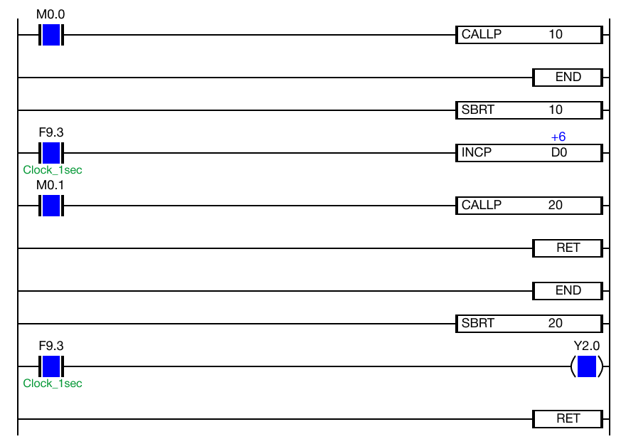
When the contacts, M0.0 and M0.1, are powered ON (1), the data register, D0, is increasing every 1 scan by the INCP instruction and the data register, Y2.0, is energizing every 1 second.
Both subroutines are being called once every scan allowing both poritons of the ladder logic to execute.