Structured Text works with select PLC CPUs. Ensure your PLC supports Structured Text.
Structure of ST Language
Identifiers
PLC Data Registers
In Structured Text programs, PLC data registers can be used directly. Data registers can be used on the right or left side of an expression. Additionally, they can be used in functions. It is similar to PLC data registers, but there is a prefix between the data register type and address, which indicates a BOOL and WORD.
| PLC Data Registers | |
|---|---|
| Item | Description |
| None | 1-bit data register |
| X | 1-bit data register |
| W | WORD (16-bit) data register |
| PLC Data Registers Example | |
|---|---|
| Example | Result |
| The value of M0.0 is 1 (turns M0.0 ON) |
| The value of M0.1 is 1 (turns M0.1 ON) |
| The value of D100 is 100 |
| The value of D101 is 0x100 (Hexadecimal) |
- Data register mapping:
- X, Y, M, L, K, F: None, X, W
- T, C, S: None, X
- D: X, W
- Z, TC, TS, CC, CS: W
Variables
A variable is a string made up of the accessible characters in a Structured Text program. There are two types of variables: Local Variable and Global Variable.
Local Variables are used within one Structured Text program. Global Variables can be used by any Structured Text program.
When registering Global Variables, it is possible to designate a specific PLC data register. Designating a specific PLC data register is known as memory allocation. If a PLC data register is not designated, internal memory will be allocated automatically.
Naming Rules
- Characters allows: alphanumeric, Korean, and
' '. - Reserved WORDs cannot be used.
- Maximum length of 32 bytes.
- If using Korean, maximum 16 characters.
- Variables are NOT case-sensitive.
Data Types
| Variable Data Types | ||
|---|---|---|
| Name (Reserved) | Data Type | Bit Size |
| SINT | Short Integer | 8 |
| INT | Integer | 16 |
| DINT | Double Integer | 32 |
| USINT | Unsigned Short Integer | 8 |
| UINT | Unsigned Integer | 16 |
| UDINT | Unsigned Double Integer | 32 |
| REAL | Float/Real Number | 32 |
| BOOL | Boolean | 1 |
| BYTE | Bit string length of 8 | 8 |
| WORD | Bit string length of 16 | 16 |
| DWORD | Bit string length of 32 | 32 |
| ARRAY | Array | - |
| STRUCT | Struct | - |
Expressions
An expression is a construct which is composed of operators and operands. The table below describes the list of operators and their priority.
| Operators | ||
|---|---|---|
| Operation | Symbols | Priority |
| Brackets | () | 1 |
| Parameter list of the function | FUNCTION_NAME(Param1, Param2, ...) | 2 |
| Index | ** | 2 |
| Singular Operator (Code) | +, - | 3 |
| Complement | NOT | 3 |
| Multiplication | * | 4 |
| Division | / | 4 |
| Modular | MOD | 4 |
| Addition | + | 5 |
| Subtraction | - | 5 |
| Comparison | <, >, <=, >= | 6 |
| Equality | = | 7 |
| Inequality | <> | 7 |
| Logical Product | &, AND | 8 |
| Exclusive OR | XOR | 9 |
| Logical Sum | OR | 10 |
- The operator with the higher priority will be operated first, and the operator with the next priority will be operated after.
- This procedure will repeat until the calculation ends.
- When operators with the same priority are used, the calculation is operated from left to right.
Arithmetic Operators
+ Operator
- The + operator adds the values on the left and right side of the operator.
- Format: Expression1 + Expression2
- In Expression1 and Expression2, a constant, PLC data register, and the expressions listed in the Operators table can be used.
| Example | |
|---|---|
| Example | Result |
| D500 = D00 + 10 |
| D10 = 50 |
- Operator
- The - operator subtracts the values on the left and right side of the operator.
- Format: Expression1 - Expression2
- In Expression1 and Expression2, a constant, PLC data register, and the expressions listed in the Operators table can be used.
| Example | |
|---|---|
| Example | Result |
| D500 = 10 |
| D10 = 10 |
* Operator
- The * operator multiplies the values on the left and right side of the operator.
- Format: Expression1 * Expression2
- In Expression1 and Expression2, a constant, PLC data register, and the expressions listed in the Operators table can be used.
| Example | |
|---|---|
| Example | Result |
| D10 = 6 |
/ Operator
- The / operator divides the values on the left and right side of the operator.
- Format: Expression1 / Expression2
- In Expression1 and Expression2, a constant, PLC data register, and the expressions listed in the Operators table can be used.
| Example | |
|---|---|
| Example | Result |
| D10 = 5 |
Dividing integers outputs the resulting integer. For example, DW10 := 3 / 2 results in D10 = 1.
MOD Operator
- The MOD operator divides the values on the left and right side of the operator and save the remainder.
- Format: Expression1 + Expression2
- Expression1 must be positive.
- Expression2 CANNOT be 0.
- In Expression1 and Expression2, a constant, PLC data register, and the expressions listed in the Operators table can be used.
| Example | |
|---|---|
| Example | Result |
| D10 = 1 (10/3 = 1) |
** Operator
- The ** operator multiplies the values on the left side of the operator to the power of the value on the right side of the value.
- Format: Expression1 ** Expression2
- Expression1Expression2
- In Expression1 and Expression2, a constant, PLC data register, and the expressions listed in the Operators table can be used.
| Example | |
|---|---|
| Example | Result |
| D10 = 1,000 (103 = 1,000) |
Comparison Operators
= Operator
- The = operator compares if two expressions are equal.
- Format: Expression1 = Expression2
- In Expression1 and Expression2, a constant, PLC data register, and the expressions listed in the Operators table can be used.
| Truth Table | ||
|---|---|---|
| Expression1 | Expression2 | Result |
| 0 | 0 | 1 |
| 0 | 1 | 0 |
| 1 | 0 | 0 |
| 1 | 1 | 1 |
| Example | |
|---|---|
| Example | Result |
| If M0.0 = 1, then Y2.A = 1 |
<> Operator
- The <> operator compares if two expressions are not equal.
- Format: Expression1 ≠ Expression2
- In Expression1 and Expression2, a constant, PLC data register, and the expressions listed in the Operators table can be used.
| Truth Table | ||
|---|---|---|
| Expression1 | Expression2 | Result |
| 0 | 0 | 0 |
| 0 | 1 | 1 |
| 1 | 0 | 1 |
| 1 | 1 | 0 |
| Example | |
|---|---|
| Example | Result |
| If M0.0 ≠ 1, then Y2.A = 1 |
< Operator
- The < operator compares if the value on the left side is less than the value on the right side.
- Format: Expression1 < Expression2
- In Expression1 and Expression2, a constant, PLC data register, and the expressions listed in the Operators table can be used.
| Truth Table | ||
|---|---|---|
| Expression1 | Expression2 | Result |
| 0 | 0 | 0 |
| 0 | 1 | 1 |
| 1 | 0 | 0 |
| 1 | 1 | 0 |
| Example | |
|---|---|
| Example | Result |
| While D0 is less than 5, D0 = D0 + 1 and D10 = D10 + D0 |
> Operator
- The > operator compares if the value on the left side is greater than the value on the right side.
- Format: Expression1 > Expression2
- In Expression1 and Expression2, a constant, PLC data register, and the expressions listed in the Operators table can be used.
| Truth Table | ||
|---|---|---|
| Expression1 | Expression2 | Result |
| 0 | 0 | 0 |
| 0 | 1 | 0 |
| 1 | 0 | 1 |
| 1 | 1 | 0 |
| Example | |
|---|---|
| Example | Result |
| While D0 is less than 10, D10 = D10 + D0 and D0 = D0 + 1. If D0 is greater than 5, exit the while loop |
<= Operator
- The <= operator compares if the value on the left side is less than or equal to the value on the right side.
- Format: Expression1 ≤ Expression2
- In Expression1 and Expression2, a constant, PLC data register, and the expressions listed in the Operators table can be used.
| Truth Table | ||
|---|---|---|
| Expression1 | Expression2 | Result |
| 0 | 0 | 1 |
| 0 | 1 | 1 |
| 1 | 0 | 0 |
| 1 | 1 | 1 |
| Example | |
|---|---|
| Example | Result |
| While D0 is less than or equal to 5, D0 = D0 + 1 and D10 = D10 + D0 |
>= Operator
- The >= operator compares if the value on the left side is greater than or equal to the value on the right side.
- Format: Expression1 ≥ Expression2
- In Expression1 and Expression2, a constant, PLC data register, and the expressions listed in the Operators table can be used.
| Truth Table | ||
|---|---|---|
| Expression1 | Expression2 | Result |
| 0 | 0 | 1 |
| 0 | 1 | 0 |
| 1 | 0 | 1 |
| 1 | 1 | 1 |
| Example | |
|---|---|
| Example | Result |
| If D0 = 0, then D10 = 10. While D10 is greater than or equal to 1, D0 = D0 + D10 and D10 = D10 - 1 |
Logical Operators
AND (&) Operator
- The AND or & operator compares the bits of two operands. If the correlated bits are both 1, the result bit is 1.
- Format: Expression1 AND Expression2 or Expression1 & Expression2
- In Expression1 and Expression2, a constant, PLC data register, and the expressions listed in the Operators table can be used.
| Truth Table | ||
|---|---|---|
| Expression1 | Expression2 | Result |
| 0 | 0 | 0 |
| 0 | 1 | 0 |
| 1 | 0 | 0 |
| 1 | 1 | 1 |
| Example | |
|---|---|
| Example | Result |
| M1.0 = 0 (M0.0 & M0.1 = 0) |
OR Operator
- The OR operator compares the bits of two operands. If the correlated bits are both 1, the result bit is 1.
- Format: Expression1 OR Expression2
- In Expression1 and Expression2, a constant, PLC data register, and the expressions listed in the Operators table can be used.
| Truth Table | ||
|---|---|---|
| Expression1 | Expression2 | Result |
| 0 | 0 | 0 |
| 0 | 1 | 1 |
| 1 | 0 | 1 |
| 1 | 1 | 1 |
| Example | |
|---|---|
| Example | Result |
| M1.0 = 1 (M0.0 OR M0.1 = 1) |
XOR Operator
- The XOR operator compares the bits of two operands. If one of the correlated bits are 1, the result bit is 1. If the correlated bits are both 1, the result is 0.
- Format: Expression1 XOR Expression2
- In Expression1 and Expression2, a constant, PLC data register, and the expressions listed in the Operators table can be used.
| Truth Table | ||
|---|---|---|
| Expression1 | Expression2 | Result |
| 0 | 0 | 0 |
| 0 | 1 | 1 |
| 1 | 0 | 1 |
| 1 | 1 | 0 |
| Example | |
|---|---|
| Example | Result |
| M1.0 = 0 (M0.0 XOR M0.1 = 0) |
NOT Operator
- The NOT operator compares the bits of two operands. If the bit of the operand is 1, the result is 0. If the bit of the operand is 0, the result is 1.
- Format: Expression1 XOR Expression2
- In Expression1 and Expression2, a constant, PLC data register, and the expressions listed in the Operators table can be used.
| Truth Table | |
|---|---|
| Expression1 | Result |
| 0 | 1 |
| 1 | 0 |
| Example | |
|---|---|
| Example | Result |
| M0.0 = 1 |
Statements
Assignment Statement
Assignment statements substitutes a value or a result from a calculation into the variable or PLC data register. The PLC data register where the constant, the value of a variable or the result of a calculation, has to be placed on the left side of the := operator. All assignment statements must end with ;.
- Format: Identifier := Expression
- Identifier can be a variable or PLC data register.
- In Expression, a constant, PLC data register, and the expressions listed in the Operators table can be used.
| Example | |
|---|---|
| Example | Result |
| The value of M0.0 is 1 |
| The value of D100 is 100 |
| The value of D500 is D0 + D1 |
Branch Statement
IF Statement
IF statements perform the operations in the statement if the condition expression result is true.
If the IF statement's condition is false and an ELSEIF statement exists, the condition of the ELSEIF statement is checked.
If all conditions are false, none of the command statements are performed unless there an ELSE statement exists.
| Format |
|---|
IF conditional expression THEN |
conditional expressionscan be composed of comparison operators or logical operators.- There can be multiple
logicstatements. - Only 1 IF and ELSE statement each can exist. Multiple ELSEIF statements can exist.
| Example |
|---|
|
CASE Statement
CASE statements branch the following operations according the expression's value.
| Format |
|---|
CASE expression OF |
expressionmust be an integer.integer optioncan be a singular integer, or multiple integers, or a range of integers.
| Integer Option | |
|---|---|
| Integer Option types | Result |
| 1 | When the expression's value is 1 |
| 2, 3, 4 | When the expression's value is 2, 3, or 4 |
| 5..10 | When the expression's value is 5, 6, 7, 8, 9, or 10 |
| 1, 2..5, 10 | When the expression's value is 1, 2, 3, 4, 5, or 10 |
- There can be multiple
logicstatements. - ELSE can only be used once or not all.
| Example |
|---|
|
Repetitive Statement
FOR Statement
FOR statements are performed to process the repetitive operations. This statement can only be used when the number of loops is definitive. If not, WHILE or REPEAT statements should be used.
If too many repetition statements are used, the scan time will increase and performance will decrease.
| Format |
|---|
FOR init expression TO expression BY expression DO |
init expressionis used to initialize the repetitive variables with an assignment statement. On the left side of the:=operator, the variable or PLC data register should exist. On the right side of the:=operator, the integer to initialize the variable or PLC data register should exist.- The
expressionthat follows TO is the final number of the repetitive variable. The integer value must be used, and thelogicstatements will be performed only when the repetitive variable's value is less than or equal to thisexpression. - The
expressionthat follows BY is the number that increases every time a loop oflogicstatements is performed. This can be omitted or an integer can be located. The value increases by 1 as default. - There can be multiple
logicstatements.
| Example |
|---|
|
WHILE Statement
WHILE statements perform a repetitive operation. WHILE statements are not limited to the number of repetitions like FOR statements.
The logic statements in a WHILE statement will be performed while the conditional expression's result is true. It will be performed forever if the conditional expression's result never becomes false.
If too many repetition statements are used, the scan time will increase and performance will decrease.
| Format |
|---|
WHILE conditional expression DO |
conditional expressions can be composed of comparison operators or logical operators.- There can be multiple
logicstatements.
| Example |
|---|
The WHILE statement's conditional expression is always true. This runs forever. |
REPEAT Statement
REPEAT statements perform a repetitive operation. REPEAT statements are not limited to the number of repetitions like FOR statements. REPEAT statements loop performs while the conditional expression after UNTIL is false. The loop will perform forever if the conditional expression doesn't become true.
Unlike the WHILE statement, the REPEAT statement operates the logic statements once, even if the conditional expression is true.
If too many repetition statements are used, the scan time will increase and performance will decrease.
| Format |
|---|
REPEAT |
logicstatements are performed whileconditional expressionis false.- The REPEAT statements terminates when
conditional expressionis true. - There can be multiple
logicstatements.
| Example |
|---|
The conditional expression after UNTIL is always false. |
Other Statements
EXIT Statement
The EXIT statement is used to escape from repetitive statements before they end. When an EXIT statement is performed, the nearest repetitive statement is cancelled.
| Example |
|---|
|
RETURN Statement
The RETURN statement is used to terminate the current process in the Structured Text program. When the RETURN statement is performed, the logic statements that follows the RETURN statement will be ignored, and the process will jump from the RETURN statement to the last part of the Structured Text program.
| Example |
|---|
|
Comment
Comments make the Structured Text program readable and easy to understand. The comments are not compiled, and they do not affect the program.
// comments the current line
(* *) comments the current line and all text in between
| Example |
|---|
|
|
Application Instructions
The Structured Text language shares the application instructions with the Ladder Diagram program.
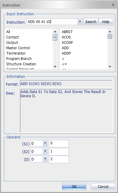
The input window of application instructions are identical to the Ladder Diagram program's. This can be open by typing F10 on the keyboard.
Enter the instruction and operand like the Ladder Diagram program and left-click OK. The instructions will automatically be converted into Structured Text format.

Auto-complete is supported.
Input Option
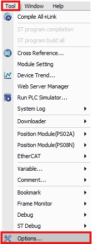
Open the Options window by left-click Tool and left-clicking Options.
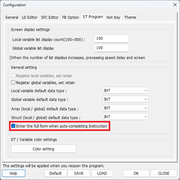
Left-click ST Program and check Enter the full form when auto-completing Instruction.

This option automatically enters commas and parentheses that match the number of operands.