Example - Ladder Diagram
BKCMP=

The BKCMP= instruction compares n number of WORD data registers starting at S1 to n number of WORD data registers starting at S2.
For each data register in the range S1 ~ Sn and S2 ~ Sn that are equal in value, each data register in the range D ~ Dn will turn bit 0 to ON (1).
Ladder Diagram Example

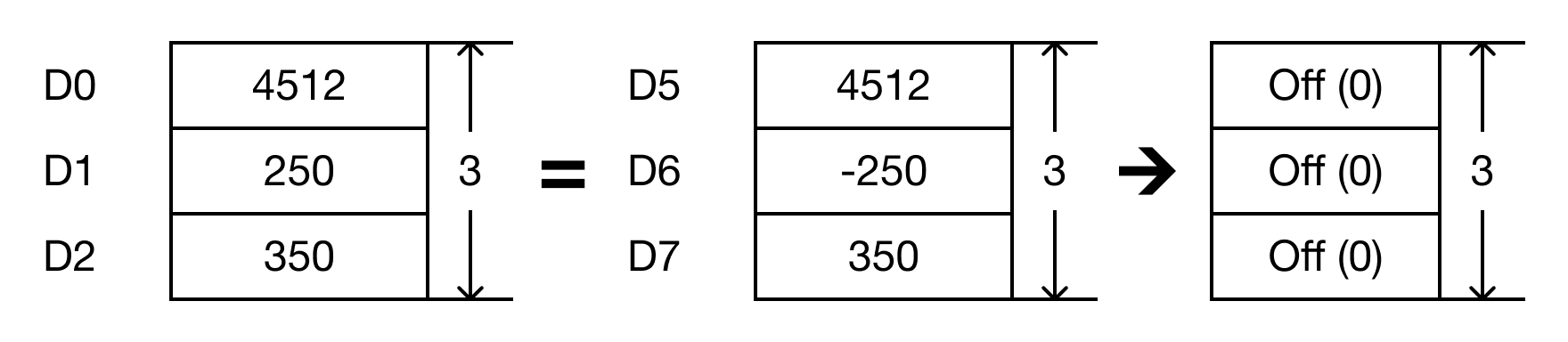
- The BKCMP= instruction will compare the following expressions for a true or false value:
- D0 = D5 → 4,512 = 4,512
- D1 = D6 → 250 = -250
- D2 = D7 → 350 = 350

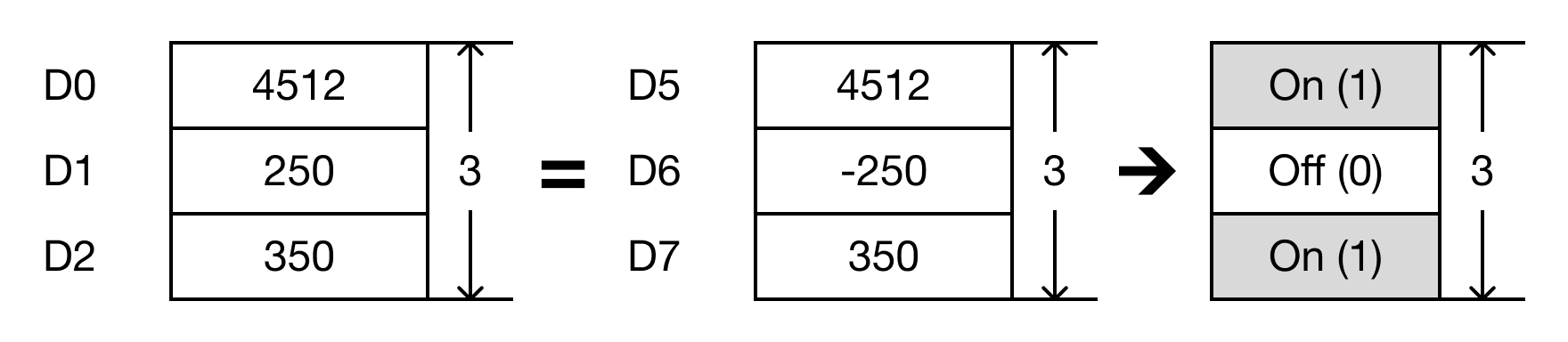
- When the open contact, M0.2, is powered ON (1), the values of the data registers are compared.
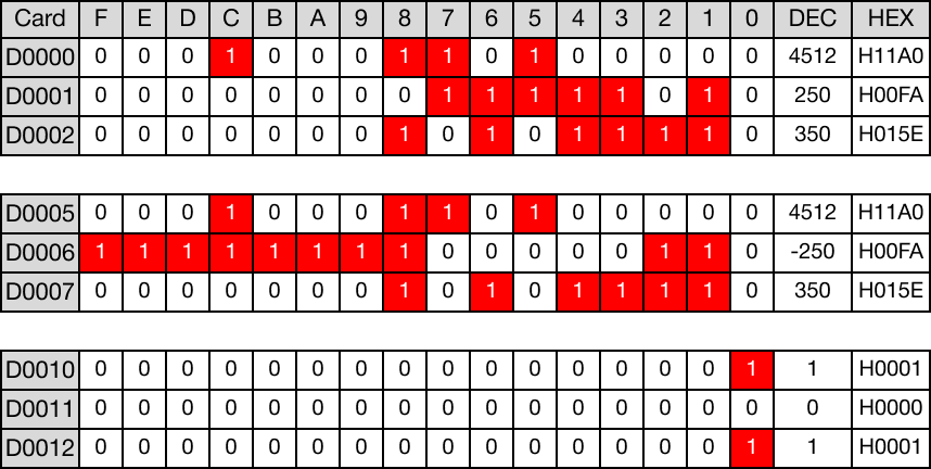
- D0 = D5 → 4,512 = 4,512 (TRUE → D10 = 1)
- D1 = D6 → 250 = -250 (FALSE → D11 = 0)
- D2 = D7 → 350 = 350 (TRUE → D12 = 1)
Memory Monitor
BKCMP=P

The BKCMP=P one-shot instruction compares n number of WORD data registers starting at S1 to n number of WORD data registers starting at S2.
For each data register in the range S1 ~ Sn and S2 ~ Sn that are equal in value, each data register in the range D ~ Dn will turn bit 0 to ON (1).
Every time this instruction executes, it energizes the output only once.
Ladder Diagram Example
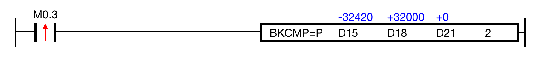
- The BKCMP=P instruction will compare the following expressions for a true or false value:
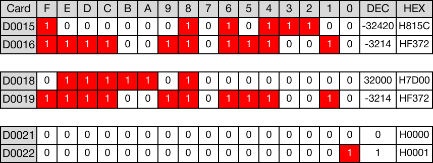
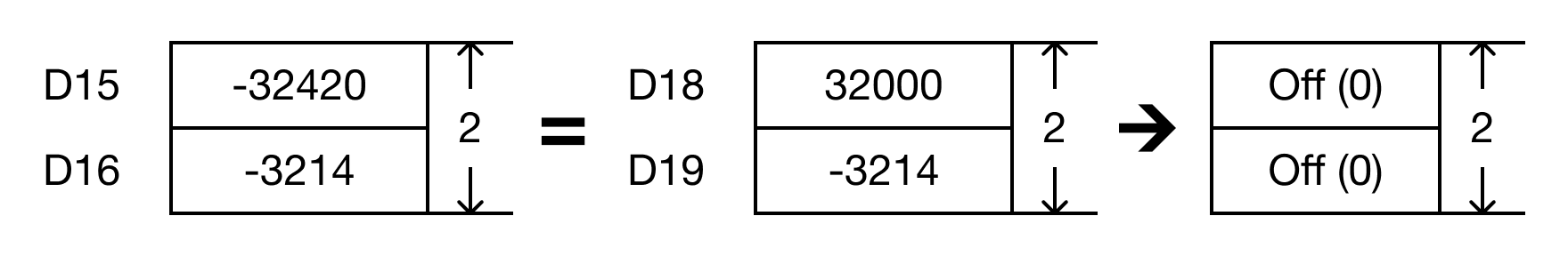
- D15 = D18 → -32,400 = 32,000
- D16 = D19 → -3,124 = -3,124
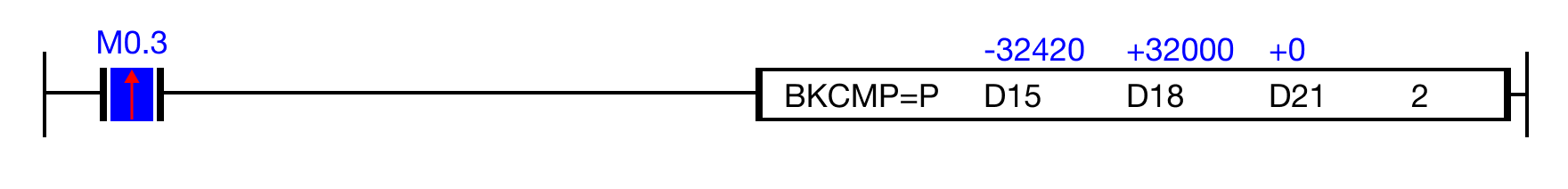
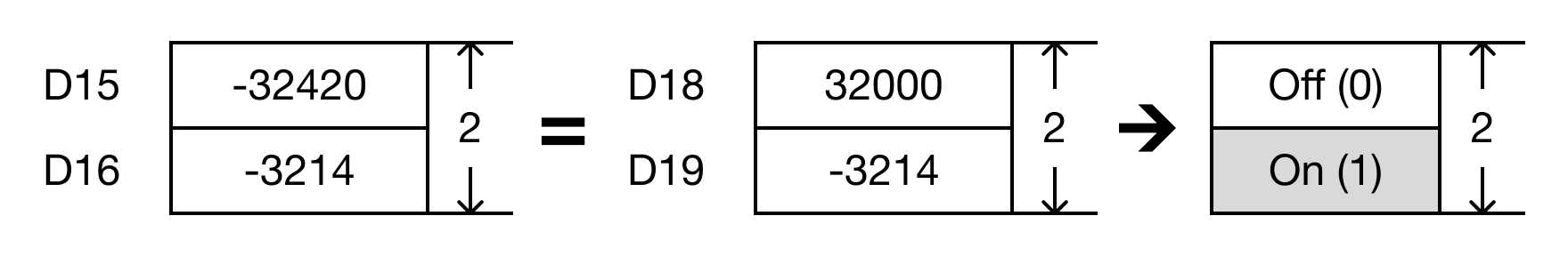
- When the open contact, M0.3, is powered ON (1), the values of the data registers are compared.
- D15 = D18 → 4,512 = 4,512 (FALSE → D21 = 0)
- D16 = D19 → 250 = -250 (TRUE → D22 = 1)
Memory Monitor