Example - Ladder Diagram
BKCMP<

The BKCMP< instruction compares n number of WORD data registers starting at S1 to n number of WORD data registers starting at S2.
For each data register in the range S1 ~ Sn that is less than each data register in the range S2 ~ Sn, each data register in the range D ~ Dn will turn bit 0 to ON (1).
Ladder Diagram Example

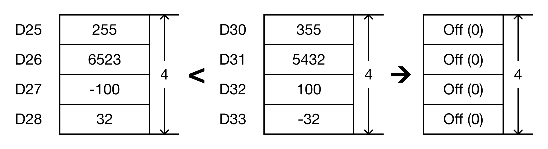
- The BKCMP< instruction will compare the following expressions for a true or false value:
- D25 < D30 → 255 < 355
- D26 < D31 → 6,523 < 5,432
- D27 < D32 → -100 < 100
- D28 < D33 → 32 < -32

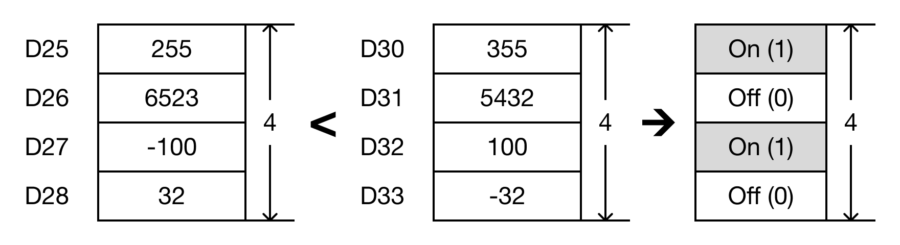
- When the open contact, M0.2, is powered ON (1), the values of the data registers are compared.
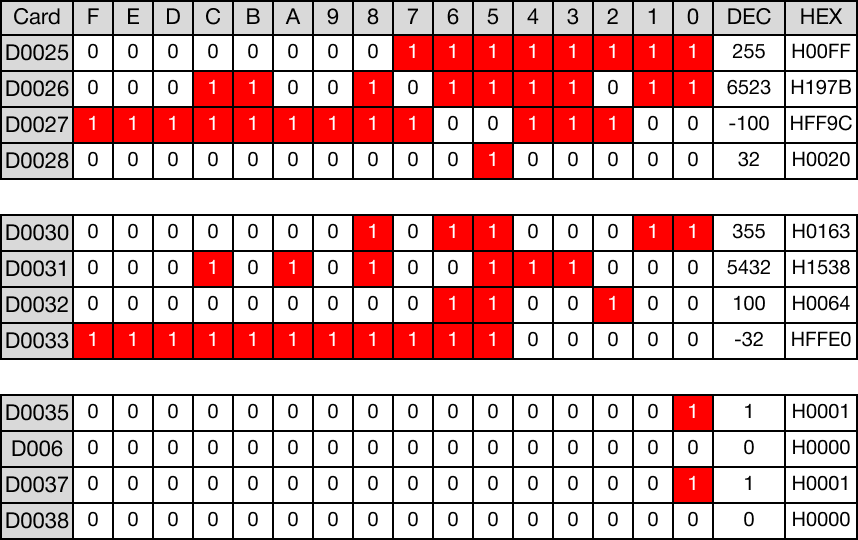
- D25 < D30 → 255 < 355 (TRUE → D35 = 1)
- D26 < D31 → 6,523 < 5,432 (FALSE → D36 = 0)
- D27 < D32 → -100 < 100 (TRUE → D37 = 1)
- D28 < D33 → 32 < -32 (FALSE → D38 = 0)
Memory Monitor
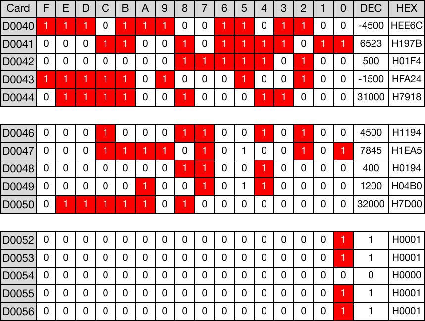
BKCMP<P

The BKCMP<P one-shot instruction compares n number of WORD data registers starting at S1 to n number of WORD data registers starting at S2.
For each data register in the range S1 ~ Sn that is less than each data register in the range S2 ~ Sn, each data register in the range D ~ Dn will turn bit 0 to ON (1).
Every time this instruction executes, it energizes the output only once.
Ladder Diagram Example
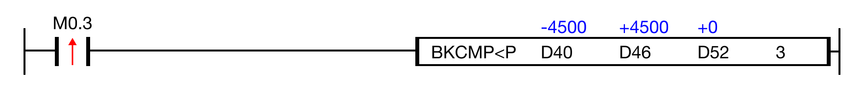
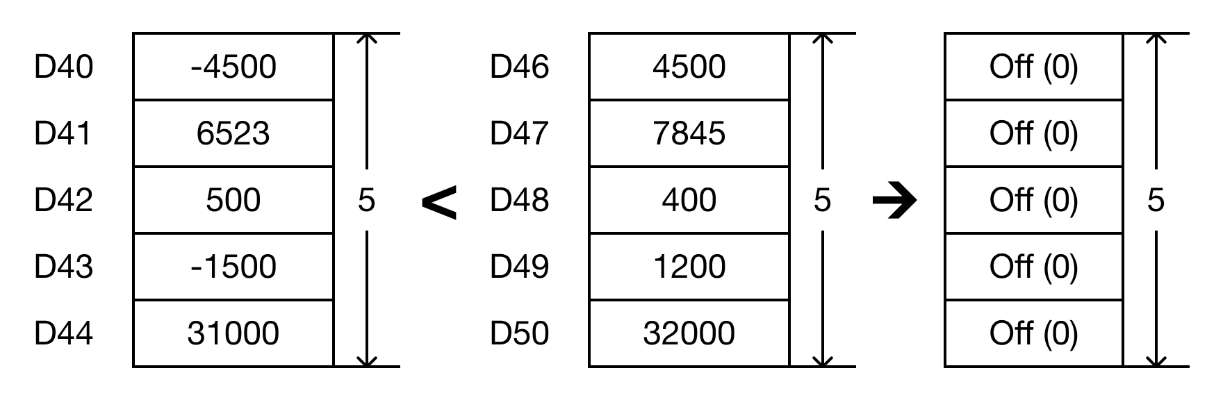
- The BKCMP<P instruction will compare the following expressions for a true or false value:
- D40 < D30 → -4,500 < 4,500
- D41 < D31 → 6,523 < 7,845
- D42 < D32 → 500 < 400
- D43 < D33 → -1,500 < -1,200
- D44 < D33 → 31,000 < 32,000
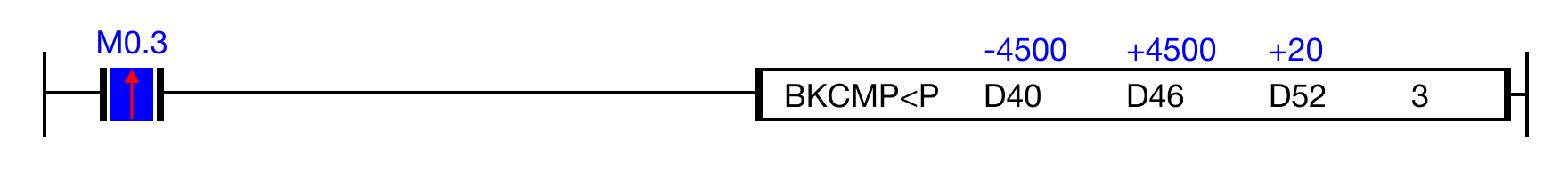
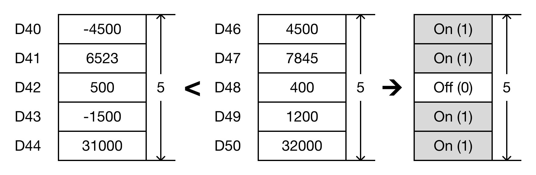
- When the open contact, M0.3, is powered ON (1), the values of the data registers are compared.
- D40 < D30 → -4,500 < 4,500 (TRUE → D52 = 1)
- D41 < D31 → 6,523 < 7,845 (TRUE → D53 = 1)
- D42 < D32 → 500 < 400 (FALSE → D54 = 0)
- D43 < D33 → -1,500 < -1,200 (TRUE → D55 = 1)
- D44 < D33 → 31,000 < 32,000 (TRUE → D56 = 1)
Memory Monitor