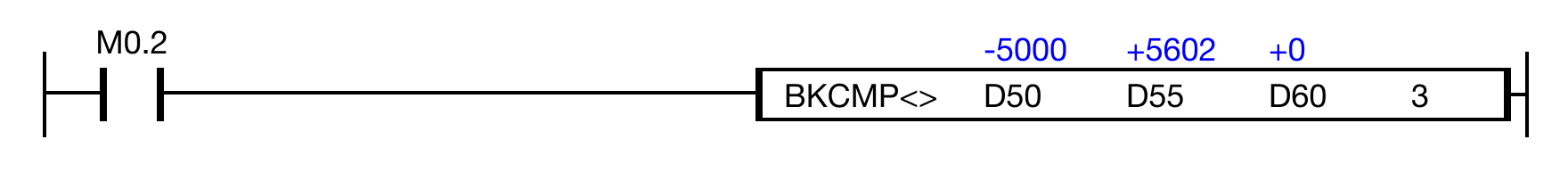
Example - Ladder Diagram
BKCMP<>

The BKCMP<> instruction compares n number of WORD data registers starting at S1 to n number of WORD data registers starting at S2.
For each data register in the range S1 ~ Sn that is not equal to each data register in the range S2 ~ Sn, each data register in the range D ~ Dn will turn bit 0 to ON (1).
Ladder Diagram Example
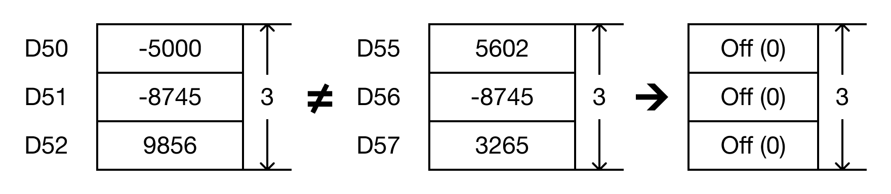
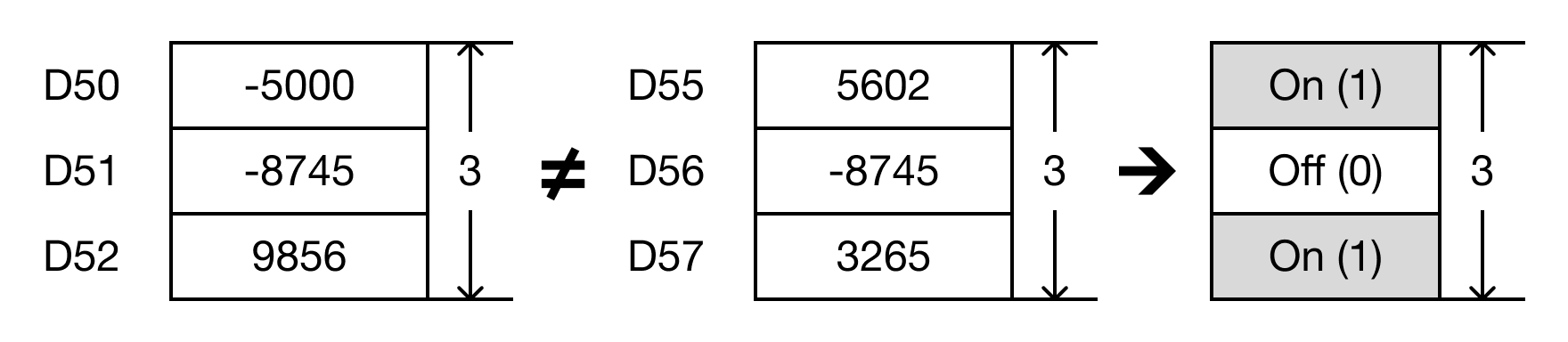
- The BKCMP<> instruction will compare the following expressions for a true or false value:
- D50 ≠ D55 → -5,000 ≠ 5,602
- D51 ≠ D56 → -8,745 ≠ -8,745
- D52 ≠ D57 → 9,856 ≠ 3,265
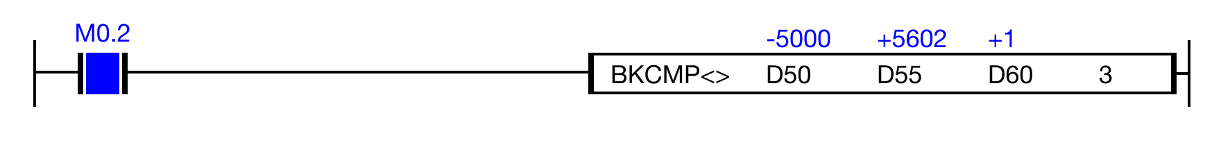
- When the open contact, M0.2, is powered ON (1), the values of the data registers are compared.
- D50 ≠ D55 → -5,000 ≠ 5,602 (TRUE → D60 = 1)
- D51 ≠ D56 → -8,745 ≠ -8,745 (FALSE → D61 = 0)
- D52 ≠ D57 → 9,856 ≠ 3,265 (TRUE → D62 = 1)
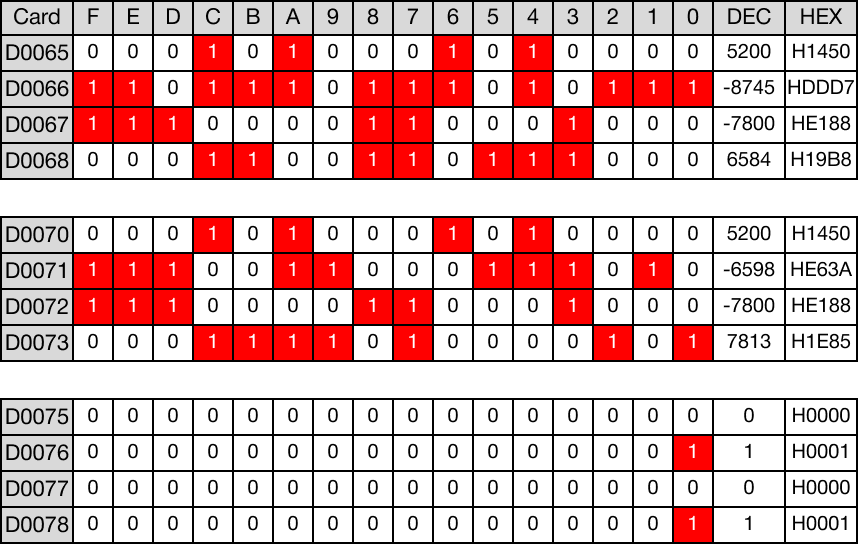
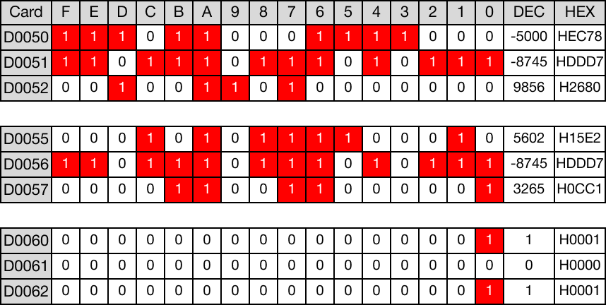
Memory Monitor
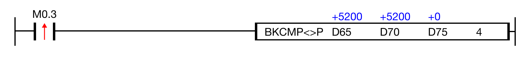
BKCMP<>P

The BKCMP<>P one-shot instruction compares n number of WORD data registers starting at S1 to n number of WORD data registers starting at S2.
For each data register in the range S1 ~ Sn that is not equal to each data register in the range S2 ~ Sn, each data register in the range D ~ Dn will turn bit 0 to ON (1).
Every time this instruction executes, it energizes the output only once.
Ladder Diagram Example
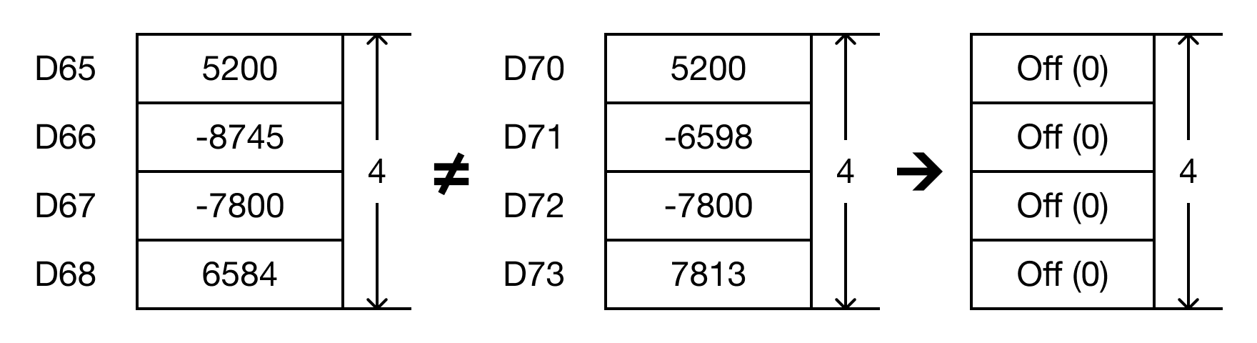
- The BKCMP<>P instruction will compare the following expressions for a true or false value:
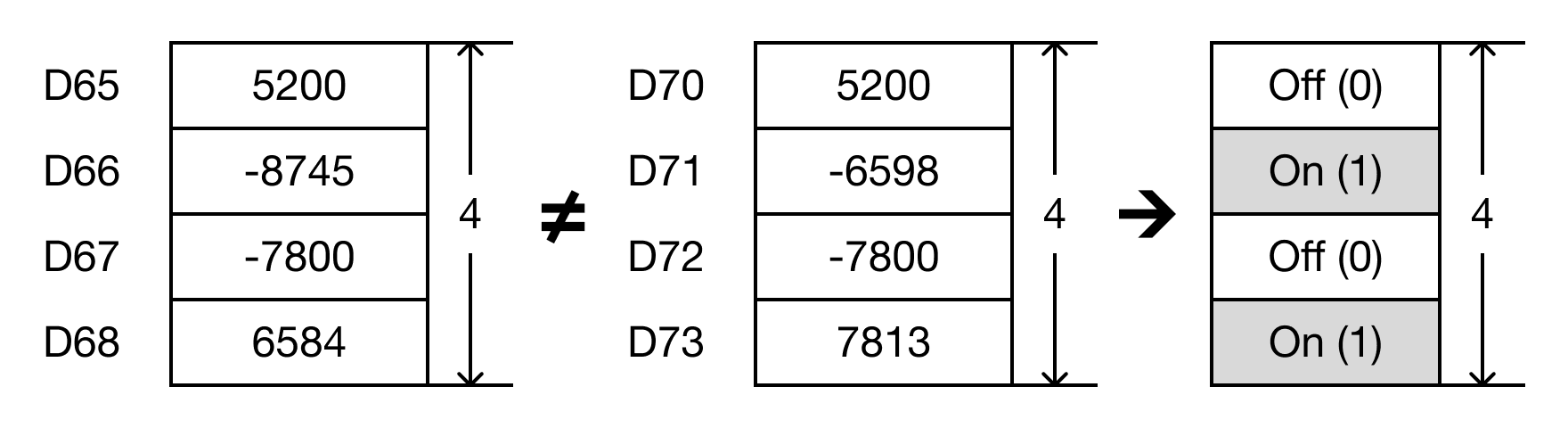
- D65 ≠ D70 → 5,200 ≠ 5,200
- D66 ≠ D71 → -8,745 ≠ -6,598
- D67 ≠ D72 → 7,800 ≠ 7,800
- D68 ≠ D73 → 6,584 ≠ 7,813

-
When the open contact, M0.3, is powered ON (1), the values of the data registers are compared.
- D65 ≠ D70 → 5,200 ≠ 5,200 (FALSE → D75 = 0)
- D66 ≠ D71 → -8,745 ≠ -6,598 (TRUE → D76 = 1)
- D67 ≠ D72 → 7,800 ≠ 7,800 (FALSE → D77 = 0)
- D68 ≠ D73 → 6,584 ≠ 7,813 (TRUE → D78 = 1)
Memory Monitor