EtherNet/IP Server Communication Program
Introduction
EtherNet/IP (Ethernet Industrial Protocol) is a widely used industrial network protocol that enables real-time communication between devices such as PLCs (Programmable Logic Controllers), HMIs, and sensors over standard Ethernet infrastructure. When a PLC is configured as an EtherNet/IP server (also known as an adapter), it acts as a data provider that responds to requests from EtherNet/IP clients (or scanners), such as SCADA systems or other PLCs.
As a server, the PLC hosts a set of predefined or custom data tags that clients can read from or write to using the Common Industrial Protocol (CIP). This setup allows for seamless integration of automation systems, real-time data exchange, and efficient control across complex industrial environments.
Setup Summary
This guide covers configuring EtherNet/IP communication between the PLC-S Plus CPU and Logix Designer. The following steps were completed:
- Configured Logix Designer by adding a new EtherNet/IP module, defining I/O connections, and setting up an MSG instruction for data exchange.
- Set up a new project in CICON, select the PLC-S Plus CPU, configured Ethernet parameters, and ensured network compatibility.
- Created Global Variables in CICON, structured as SINT arrays, and assigned them as EtherNet/IP tags for communication.
- Established a connection between CICON and the PLC, ensuring the correct IP settings and verifying successful communication.
- Monitored real-time data exchange, verifying that values input in CICON appeared correctly in Logix Designer.
- Finalized in Logix Designer by downloading the program, switching to RUN mode, and confirming data transmission between the two systems.
Background Information
This guide will cover enabling and using the EtherNet/IP server feature offered on the PLC-S Plus CPU.
Requirements
- PLC-S Plus CPU
- CICON v8.21.18 or higher
- 2 straight-through Ethernet cables
- RJ45 Ethernet cables are required to connect the PLC-S Plus to a network
- Power supply for the PLC-S Plus
- USB-C Cable to connect to the PLC-S Plus and CICON
CICON Setup
Project Setup
Step 1: Setting Up a New Project
- Open CICON and select New Project.
- In the Set Project Details window:
- Project Path: Choose a directory for the project files.
- CPU Type: Select CM3 SPLUS (ensure this matches the hardware).
- Project Name: Assign a recognizable name (e.g., Prj0131_1241).
- Developer Name: Enter the developer's name (optional).
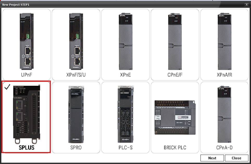
- Setting the correct CPU type is essential, as EtherNet/IP Server is only available on PLC-S Plus.
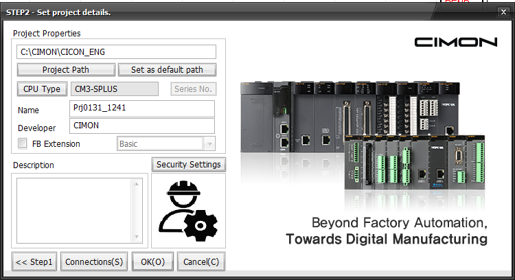
- Click OK to proceed.
Step 2: Creating a New Program
- In the Project Window, right-click Program.
- Select New Program to create a new logic program.
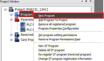
This step initializes a new logic program where the PLC instructions will be defined.
Step 3: Accessing the New Program Menu
- Alternatively, go to File > New Program (Ctrl+N) to create a new program.
- This provides another way to initiate program creation.

Multiple methods exist to create a new program, offering flexibility in workflow.
Step 4: Configuring the New Program
- In the New Program window:
- Program Name: Assign a name (Pgm000 by default).
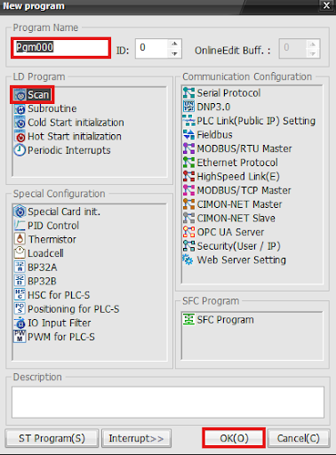
- Click OK to finalize the program setup.
Enabling Ethernet Protocol ensures the PLC can communicate over the network using EtherNet/IP.
Step 5: Accessing PLC Ethernet Settings
- In the Project Window, navigate to:
- Parameter > PLC Parameter.

- Click on the Ethernet tab at the top.
- Under IP Setting
- IP Address: 192.168.1.51
- Subnet Mask: 255.255.255.0
- Gateway: 192.168.1.1
- Under IP Setting Port2
- IP Address: 192.168.1.30
- Subnet Mask: 255.255.255.0
- Gateway: 192.168.1.1
- Under IP Setting
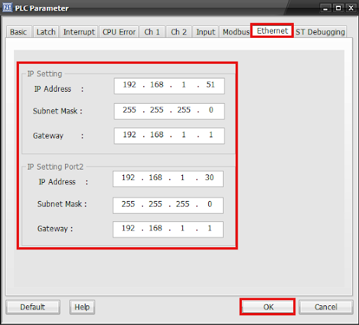
- Click OK to save.
This section allows configuring the PLC’s network parameters for Ethernet communication.
Ensure the IP addresses match the Logix Designer configuration to establish proper communication.
Step 6: Creating Global Variables
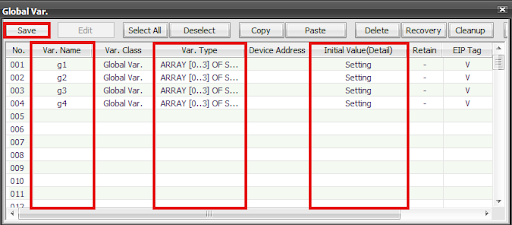
- Navigate to Global Variables in CICON.
- Define new variable names (g1, g2, g3, g4).
- Set the Variable Class as Global Var.
- Specify the Variable Type as ARRAY [0..3] OF SINT.
- Ensure the EIP Tag column is marked with V.
Global variables allow data sharing across the system, and marking them as EIP Tags ensures they are accessible via EtherNet/IP.
Step 7: Defining Array Data Type
- In the Array Setting window:
- Set the Array Data Type to SINT.
- Choose 1D Array and specify the size as 3 (to match Logix Designer).
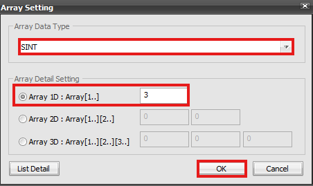
- Click OK to confirm.
SINT arrays ensure compatibility with Logix Designer's tag structure for EtherNet/IP data exchange.
Step 8: Saving the Configuration
- Click Save to apply the changes.
- Verify that all variables are properly listed under Global Variables.
Saving ensures the system stores and recognizes the variables for EtherNet/IP communication.
Step 9: Accessing the EIP Tag Configuration
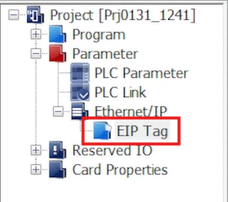
- In the Project Window, navigate to:
- EtherNet/IP > EIP Tag.
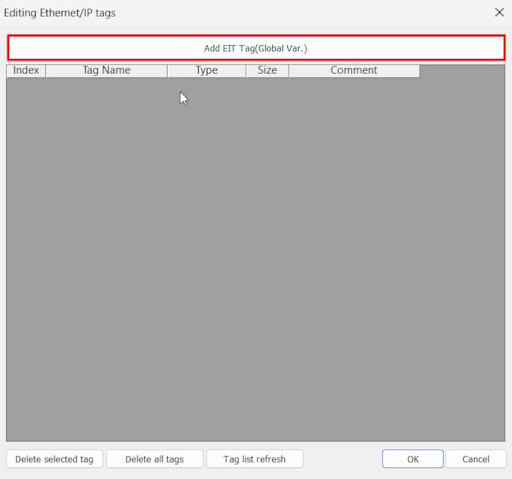
- Double-click EIP Tag to open the Editing EtherNet/IP Tags window.
This section maps global variables as EtherNet/IP tags for data exchange.
Step 10: Adding EIP Tags
- Click Add EIP Tag (Global Var.) to open the tag selection window.
- Select the Global Variables (g1, g2, g3, g4).
- Click Insert to add them as EIP Tags.
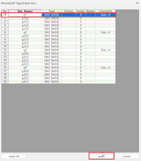
This step ensures that the selected global variables can be accessed via EtherNet/IP.
Step 11: Verifying Tag Properties
- Ensure that each tag has the following properties:
- Tag Name: g1, g2, g3, g4
- Type: SINT [INT8]
- Size: 4
- Comment: ARRAY [0..3] OF SINT
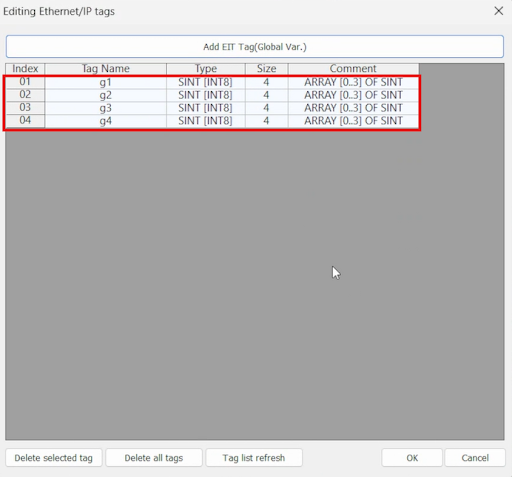
- Click OK to save the configuration.
These tags must match the data structure expected in Logix Designer for seamless communication.
Logix Designer Setup
To integrate the PLC-S Plus into Logix Designer using EtherNet/IP, follow the steps below to install and register the Electronic Data Sheet (EDS) file. This will allow Logix Designer to recognize the PLC-S Plus as a valid Ethernet device.
Setup Process
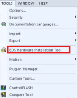
Step 1: Access the EDS Hardware Installation Tool
- In Logix Designer, navigate to the top menu bar.
- Click on Tools.
- Select EDS Hardware Installation Tool (highlighted in red).
- This tool allows users to register, unregister, and manage EDS files, ensuring that Logix Designer can recognize third-party devices like the PLC-S Plus.
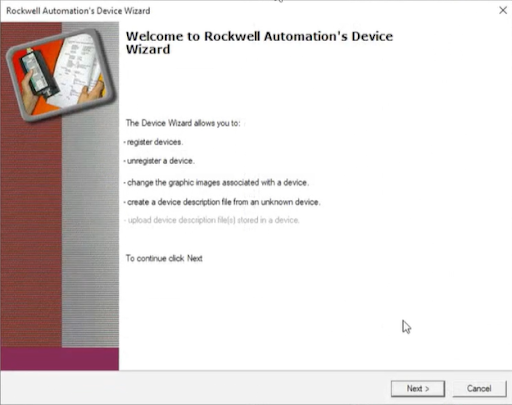
Step 2: Open the Rockwell Automation Device Wizard
- After selecting the EDS Hardware Installation Tool, the Rockwell Automation Device Wizard window will appear.
- This wizard allows you to:
- Register new devices (which we will do in the next steps).
- Unregister devices that are no longer needed.
- Modify graphic representations for devices in the system.
- Click Next to proceed.
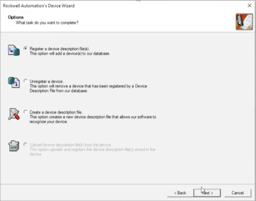
Step 3: Select the Registration Option
- The wizard will present several options:
- Register a device description file (Select this option to add the PLC-S Plus).
- Unregister a device (Used to remove a device from the database).
- Create a device description file (For custom or unknown devices).
- Upload a device description file from a device (Disabled in this case).
- Choose Register a device description file and click Next.
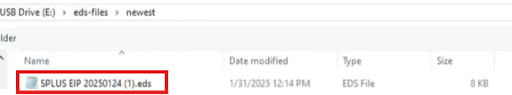
Step 4: Locate the .EDS File for the PLC-S Plus
- Browse to the location of the .EDS file on your system.
- For this guide, the PLC-S Plus EDS file is named "SPLUS EIP 20250124 (1).eds" and is stored on a USB drive under E: > eds-files > newest.
- Select the .EDS file and click Open to load it into the wizard.
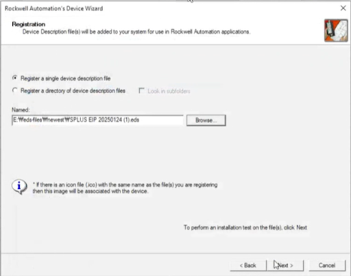
Step 5: Register the .EDS File
- The wizard will now show the selected EDS file path for registration.
- Ensure that Register a single device description file is selected.
- Click Next to proceed with the installation.
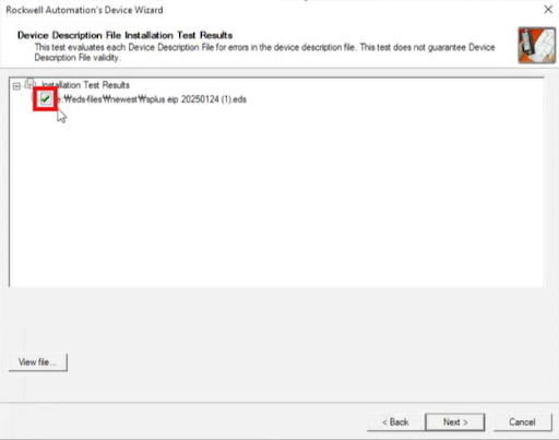
Step 6: Confirm EDS File Installation
- The system will test the EDS file for errors.
- If successful, you will see a green checkmark next to the EDS file name (highlighted in red).
- This confirms that the EDS file is valid and ready for use.
- Click Next to continue.
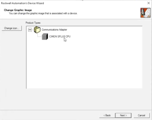
Step 7: Assign a Graphic Representation
- The wizard allows you to assign an icon to the newly registered PLC-S Plus device.
- The system automatically detects the device type as a Communications Adapter with the PLC-S Plus CPU label.
- Click Next to proceed.
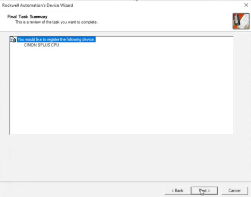
Step 8: Final Confirmation and Registration
- This summarizes the registration details.
- It confirms that the PLC-S Plus CPU has been successfully added to Logix Designer.
- Click Next to finalize the registration.
Completion
- The PLC-S Plus is now recognized in Logix Designer and can be used in EtherNet/IP communication.
- You can now proceed with setting up communication between CICON and Logix Designer.
Add a New Ethernet Module
Step 1: Adding a New Ethernet Module
- Open Logix Designer and navigate to the Controller Organizer.
- Under I/O Configuration, locate Ethernet.
- Right-click on Ethernet, then select New Module.
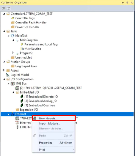
This step is essential for adding a new module to communicate over EtherNet/IP.
Step 2: Selecting the PLC-S Plus CPU Module
- In the Select Module Type window, use the search bar to type "CIMON".
- The PLC-S Plus CPU module should appear in the list.
- Select 05E3_000C_0001 - CIMON SPLUS CPU, categorized as a Communications Adapter.
- Click Create to add the module.
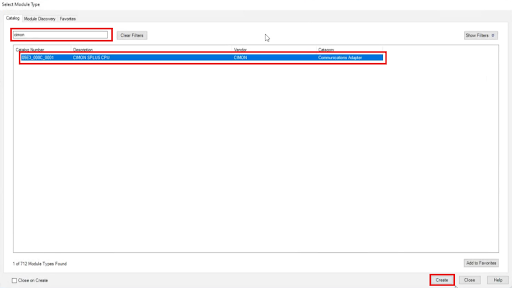
This step ensures that the correct module is added to the project.
Step 3: Configuring Module General Settings
- In the New Module window:
- Set the Name field (e.g., "cimontest").
- Under Ethernet Address, choose Private Network.
- Set the IP Address (e.g., 192.168.1.30).
- Click Change… to modify additional parameters if needed. This setting is used to set up an implicit connection, which is covered below in the Module Definition section.
- Click OK to save the configuration.
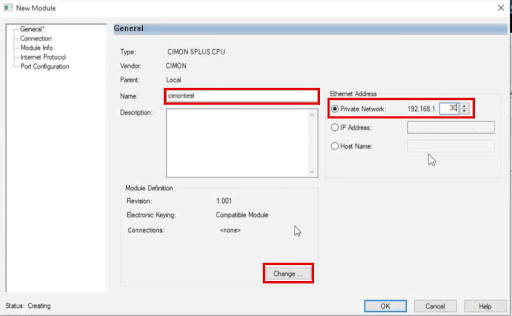
The IP address must match the configuration set in CICON to ensure proper communication.
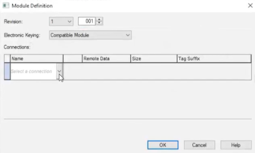
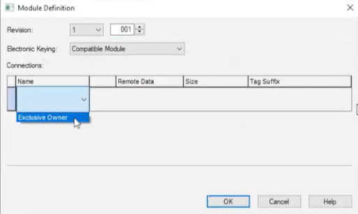
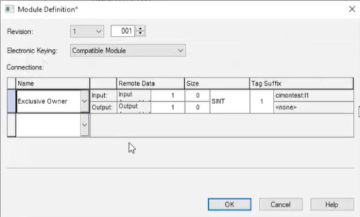
Step 4: Defining Module Connections
-
In the Module Definition window:
- Select a connection type by clicking the dropdown under Name.
- Choose Exclusive Owner.
- Select a connection type by clicking the dropdown under Name.
-
Define Remote Data Settings:
- Input Instance: (e.g., 1)
- Output Instance: (e.g., 1)
-
Define Size Settings:
- Input Data Size: (e.g., 0 byte) SINT
- Output Data Size : (e.g., 0 byte) SINT
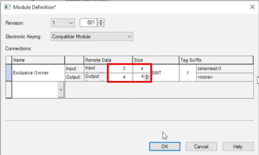
- Adjust the Size Parameters:
- Modify Input Size (e.g., 0 to 4).
- Modify Output Size (e.g., 0 to 4).
- Adjust Remote Data Parameters
- Modify Input Remote Data (e.g., 1 to 3).
- Modify Output Remote Data (e.g., 1 to 4).
Assign Tag Suffixes:
- Example: cimontest:I1 for Input.
- Example: cimontest:O1 for Output.
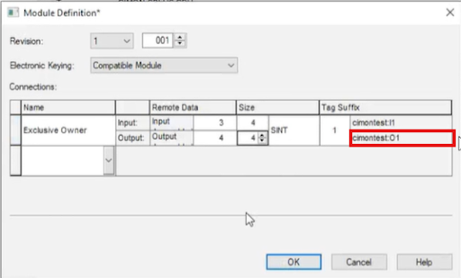
- Click OK to finalize the settings.
The input and output sizes determine how much data is exchanged. Ensure they match the expected values from CICON.
Step 5: Confirming Changes
- A Logix Designer confirmation prompt will appear.
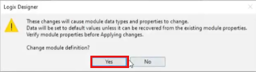
- Click Yes to apply the module definition changes.
This step ensures that the module settings are updated within the Logix Designer project.
Step 6: Reviewing Input and Output Tags
- Navigate to the Monitor Tags section in Logix Designer.
- Locate the created tags cimontest:I1 and cimontest:O1.
- Observe that the tags are associated with specific memory locations:
- cimontest:I1 → .05E3:000C_0001_85D36DB4:0
- cimontest:O1 → .05E3:000C_0001_AAB94180:0
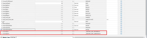
These tags represent the mapped Input and Output data from the PLC-S Plus module. They serve as the communication bridge between Logix Designer and the external PLC.
Step 7: Expanding and Inspecting Data Values
- Expand cimontest:I1 and cimontest:O1 to reveal individual data points.
- Verify that:
- cimontest:I1.Data contains 4 elements, ensuring input data is received properly.
- cimontest:O1.Data contains 4 elements, ensuring output data is sent correctly.
- Check the decimal values of each data index to confirm expected values.
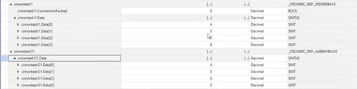
Ensure that data values are correctly updated in real-time. Any inconsistencies may indicate configuration or network communication issues.
Project Set-Up
Step 1: Adding a New Rung and Inserting an MSG Instruction
- Open the Ladder Logic Editor in Logix Designer.
- Click the Add Rung (+) button from the toolbar.
- Insert a Bit instruction that will act as the triggering condition for the message operation.
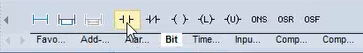
A rung is necessary to execute the message instruction within the PLC scan cycle.
Step 2: Searching for and Assigning a Timer Tag
- Open the Controller Tags window.
- Use the search bar to find the SampleRate tag.
- Ensure that SampleRate is of TIMER data type.
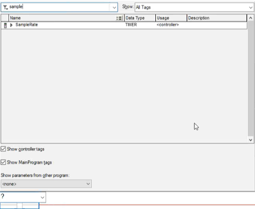
This timer will control when the MSG instruction is triggered.
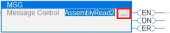
Step 3: Configuring the MSG Instruction
- On the newly created rung, enter SampleRate.DN as the triggering condition.

- Drag and place an MSG (Message Control) Instruction on the rung.

![]()
- Enter a new message tag in the MSG box, e.g., AssemblyRead2.
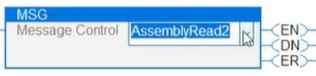
The MSG instruction sends and receives data between devices over EtherNet/IP.
Step 4: Creating a New Message Tag
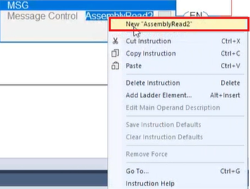
- Right-click on AssemblyRead2 inside the MSG instruction.
- Select New 'AssemblyRead2' from the dropdown.
- In the New Tag window:
- Name: AssemblyRead2.
- Type: Base.
- Data Type: MESSAGE.
- Scope: L27ERM_COMM_TEST (or the appropriate scope for your project).
- External Access: Read/Write.
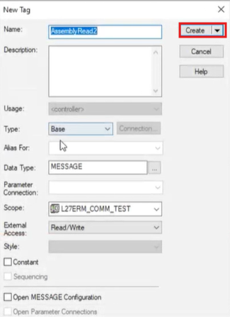
- Click Create to finalize the tag creation.
This step ensures that the message instruction is correctly assigned to a tag that will store the message configuration.
Step 5: Verifying the Message Tag Configuration
- Navigate back to the Monitor Tags section.
- Locate AssemblyRead2 in the tag list.
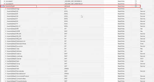
- Expand the tag to check its attributes, including:
- Flags (EN, DN, ER)
- Request Length (REQ_LEN)
- Destination Node
- Instance, Class, and Attribute
These parameters are essential for defining how the message instruction communicates with the remote device.
Step 6: Opening the Message Configuration
- Click on the “…” (ellipsis) next to AssemblyRead2 in the MSG instruction.
- The Message Configuration window appears.
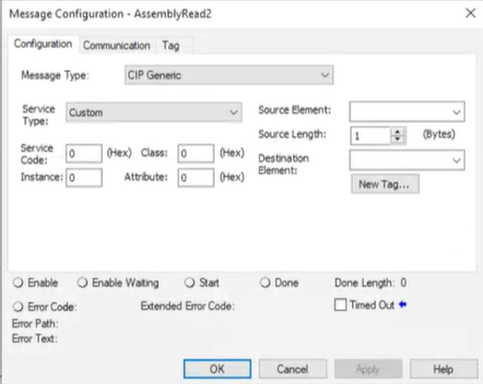
This window lets users define how data will be transmitted between the Logix Designer and CICON PLC.
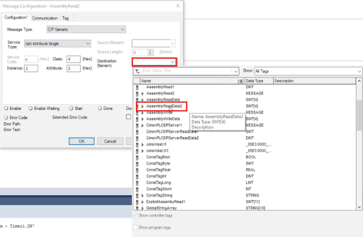
Step 7: Selecting the Message Type
- In the Message Type dropdown, select CIP Generic.
- For Service Type, select Get Attribute Single.
- Set the following parameters:
- Class: 4 (Hex)
- Instance: 1
- Attribute: 3
- Click on New Tag to define the Destination Element.
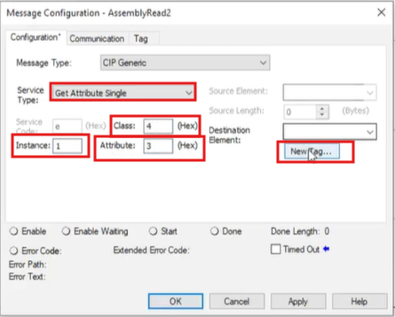
This configuration retrieves a single attribute from the remote PLC.
Step 8: Creating the Destination Tag
- In the New Tag window:
- Name: AssemblyReadData2
- Data Type: Click the dropdown button.
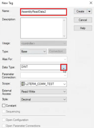
- In the Select Data Type window:
- Choose SINT[4] (4-byte array for data storage).
- Set Dim 0 = 4 (ensuring an array size of 4 elements).
- Click OK to save.
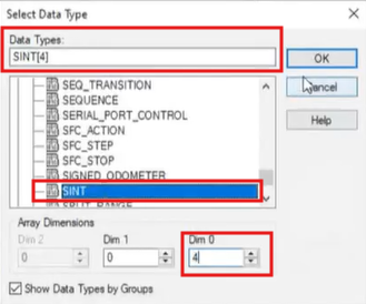
This tag stores the received data from the PLC-S Plus.
Step 9: Assigning the Destination Element
- In the Message Configuration window, set the Destination Element to AssemblyReadData2.
- Click OK to save the configuration.
At this point, the message instruction is fully configured to read data from the remote PLC.
Step 10: Opening the Communication Tab
- In the Message Configuration window, navigate to the Communication tab.
- Click the Browse button next to the Path field.
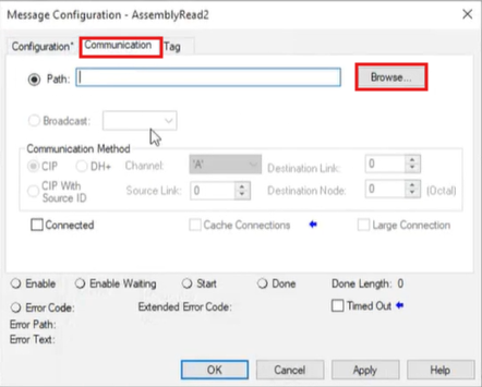
This step allows users to select the correct communication path for sending and receiving data.
Step 11: Selecting the Correct Path
- In the Message Path Browser window:
- Type "cimontest" in the search field.
- Select the Ethernet device 05E3_000C_0001 cimontest.
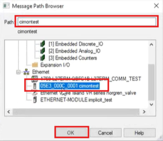
- Click OK to confirm.
This ensures that the MSG instruction is routed to the correct EtherNet/IP device for communication.
Step 12: Applying the Communication Path
- The Path field should now display "cimontest".
- Click Apply to save the communication settings.
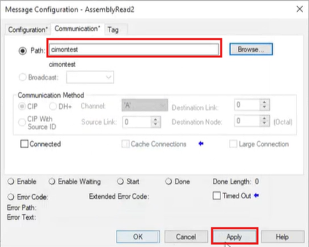
This step finalizes the network path between Logix Designer and the CICON PLC.
Step 13: Checking for Errors
- Verify that the Error Path field also shows "cimontest".
- If an error appears, recheck the module name and connection settings.
- Click Apply again if necessary.
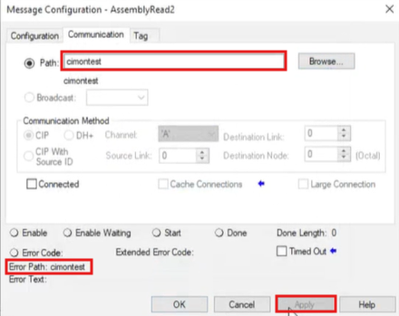
A properly configured path ensures smooth data exchange between devices.
Download and Monitor
Step 1: Selecting Connection Option
- Navigate to Online > Connect Option.

- This will open the Communication Setup window.
This step is required to define how the PC communicates with the PLC.
Step 2: Configuring Ethernet Communication
- In the Communication Setup window:
- Select Ethernet (E) as the connection type.
- Choose the IP Address and enter 192.168.1.51 (this must match the previously assigned IP).
- Click Ping Test to check connectivity.
- Set Timeout to 2 seconds and Retry to 2 times.
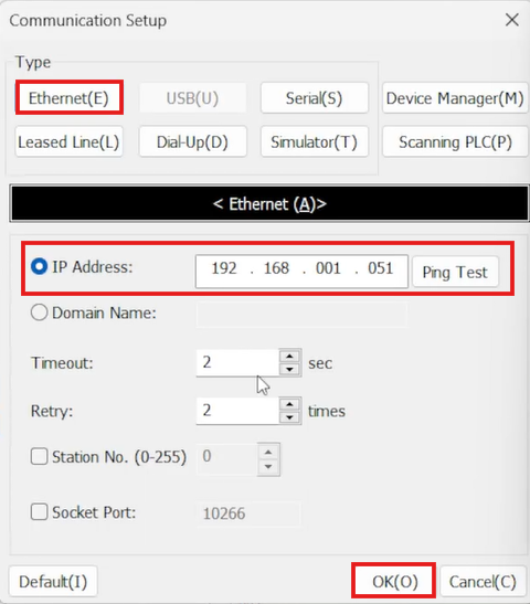
- Click OK to save and close.
A successful Ping Test confirms that the PC can communicate with the PLC over the network.
Step 3: Linking, Downloading, and Monitoring
- Navigate to Online > Link+Download+Monitor.
- This process:
- Links the PC to the PLC.
- Downloads the project to the PLC.
- Enables real-time monitoring of PLC operations.

This step ensures that all settings, tags, and configurations are transferred and active in the PLC.
Step 4: Checking Initial Values in Global Variables
- Navigate to Global Variables.
- Locate each tag's Initial Value/Detail column (g1, g2, g3, g4).
- Click on Setting to modify or initialize values.
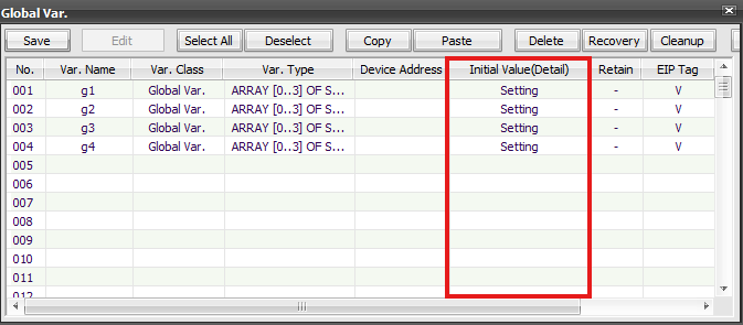
Ensuring the initial values are set correctly helps validate the data flow when communication begins.
Step 5: Monitoring Real-Time Data
- Open the Defining User Data Types window for g1.
- Observe the Monitoring column:
- Initially, all values are 0 (indicating no data change).
- Let the PLC run in online mode to allow real-time data updates.
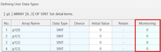
Monitoring in real-time helps verify that Logix Designer and CICON are successfully exchanging data.
Step 6: Verifying Data Updates
- After entering the values 1, 5, 78, and 6 into the Monitoring column in CICON, we will check Logix Designer to see if they appear.
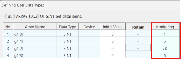
If the values in Logix Designer correctly reflect the ones set in CICON, the EtherNet/IP communication will work as intended.
Step 7: Downloading the Program to the Controller
- Ensure that you are in Offline Mode.
- Click on the Controller Menu and select Download.
- Wait for the program to transfer to the Logix PLC.
Step 8: Switching the Controller to Run Mode
- After the download is complete, click on the Controller Mode Menu.
- Select Run Mode to start execution.
- Verify that the controller is in Remote Program (Rem Prog) mode.
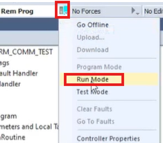
Switching to Run Mode allows the Logix PLC to execute the program and start communicating with CICON over EtherNet/IP.
Step 9: Verifying Data Exchange in Monitor Tags
- Navigate to Monitor Tags in Logix Designer.
- Expand AssemblyRead2 to check for received values.
- Confirm that the values (1, 5, 78, 6) match the ones input in CICON.
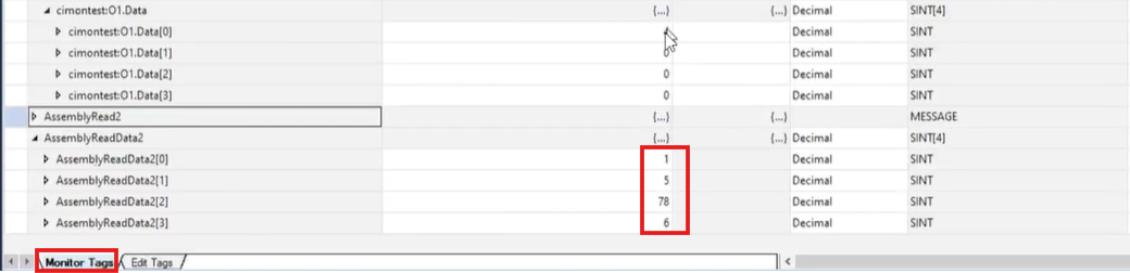
If the values in Logix Designer match those in CICON, EtherNet/IP communication is successfully established.