PID Control Initialization
- The PIDINIT instruction checks the items and initializes the data registers set up for a PID operation.
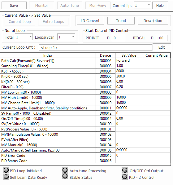
- The PID Control Special Program:
- If the value of each item is 0, that item is not used in the PID calculation.
PID Control Initialization
| PID Initialization | ||||
|---|---|---|---|---|
| Offset | Item | Description | Range | Note |
| 0 | Number of Loops | - | 1 ~ 32 1 ~ 64 | Common for All Loops |
| +1 | Number of Loops for a Scan | - | 1 ~ 32 1 ~ 64 | |
| +2 (0) | Operation Type | Forward Action: 0 Reverse Action: 1 | 0 or 1 | For Loops |
| +3 (+1) | Sampling Interval (Ts) | 0.01s ~ 60.00s | 1 ~ 6,000 | |
| +4 (+2) | Proportional Gain (Kp) | 0.01 ~ 300.00 | 1 ~ 30,000 | |
| +5 (+3) | Integral Gain (Ki) | 0.00s ~ 300.000s | 0 ~ 30,000 | |
| +6 (+4) | Derivative Gain (Kd) | 0.00s ~ 300.00s | 0 ~ 30,000 | |
| +7 (+5) | Filter Coefficient (α) | 0.00 ~ 1.00 | 0 ~ 100 | |
| +8 (+6) | Manipulation Value Low Limit (MVLL) | 0 ~ 16,000 | 0 ~ 16,000 | |
| +9 (+7) | Manipulation Value High Limit (MVHL) | 0 ~ 16,000 | 0 ~ 16,000 | |
| +10 (+8) | Variation Rate Limit of Manipulation Value (ΔMVL) | 0 ~ 16,000 | 0 ~ 16,000 | |
| +11 (+9) | Use of Manipulation Value Automatic Apply | Don't Use: 0 Use: 1 | 0 or 1 | |
| +12 (+10) | Set Value Transition Step | 0 ~ 1,000 times | 0 ~ 1,000 | |
| +13 (+11) | Process Value Inertia Amount | 0 ~ 16,000 | 0 ~ 16,000 | |
| +14 (+12) | ON/OFF Control Time | 1.00s ~ 60.00s | 1 ~ 6,000 Don't Use: 0 | |
| +15 (+13) | PIDINIT Operation Status | Indicates Errors | Operation Status | |
| +16 (+14) | FLAGS | - | - | Not Available |
| +17 (+15) | Reserved | - | - | |
| +18 (+16) | Auto Tuning Counter 1 | - | - | |
| +19 (+17) | Auto Tuning Counter 2 | - | - | |
| +20 (+18) | ON/OFF Control Counter | - | - | |
| +21 (+19) | Sampling Counter | - | - | |
Common Setting Data
| Common Setting Data | ||
|---|---|---|
| Offset | Item | Description |
| 0 | Number of Loops |
|
| +1 | Number of Loops per Scan |
|
Setting Data For Each Loop
| Setting Data For Each Loop | ||
|---|---|---|
| Offset | Item | Description |
| +2 | Operation Type |
|
| +3 | Sampling Interval (Ts) |
|
| +4 | Proportional Gain (Kp) |
|
| +5 | Integral Gain (Ki) |
|
| +6 | Derivative Gain (Kd) |
|
| +7 | Filter Coefficient (α) |
|
| +8 | Manipulation Value Low Limit (MVLL) |
|
| +9 | Manipulation Value High Limit (MVHL) |
|
| +10 | Variation Rate Limit of Manipulation Value (ΔMVL) |
|
| +11 | Use of Manipulation Value Automatic Apply |
|
| +12 | Set Value Transition Step |
|
| +13 | Process Value Inertia Amount |
|
| +14 | ON/OFF Control Time |
|
| +15 | PID Operation Status |
|

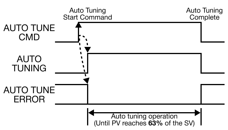
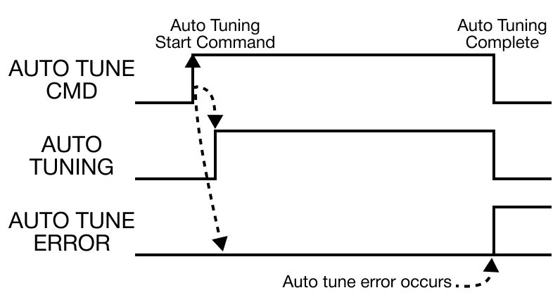
PID Flags
| PID Flags | ||
|---|---|---|
| Bit | Flag | Description |
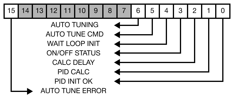 | ||
| 0 | PID-INIT OK |
|
| 1 | PID CALC |
|
| 2 | CALC DELAY |
|
| 3 | ON/OFF STATUS |
|
| 4 | WAIT LOOP INIT |
|
| 5 | AUTO TUNE CMD |
|
| 6 | AUTO TUNING |
|
| F | AUTO TUNE ERROR |
|