Positioning for PLC-S Special Program Parameters
CM3 Positioning Parameters
| Positioning Parameters | |||||
|---|---|---|---|---|---|
| Offset | Item | Configurations | Memory | Note | |
| Default | Function | ||||
| 0 | Select Pulse Output | 0 | Not Used: 0 High Active: 1 Low Active: 2 | WORD | - |
| +1 | Bias Speed | 1 | 1 ~ 100,000pps | DWORD | Low WORD |
| +2 | High WORD | ||||
| +3 | Speed Limit | 50,000 | Low WORD | ||
| +4 | High WORD | ||||
| +5 | Acceleration/Deceleration Time 1 | 1,000 | 1 ~ 65,535ms | WORD | - |
| +6 | Acceleration/Deceleration Time 2 | - | |||
| +7 | Acceleration/Deceleration Time 3 | - | |||
| +8 | Acceleration/Deceleration Time 4 | - | |||
| +9 | Software Upper Limit | 2,147,483,647 | -2,147,483,648 ~ 2,147,483,647 | DWORD | Low WORD |
| +10 | High WORD | ||||
| +11 | Software Lower Limit | -2,147,483,648 | Low WORD | ||
| +12 | High WORD | ||||
| +13 | Position Address Under Speed Control | 0 | Don't Update: 0 Update: 1 Clear/Update: 2 | WORD | - |
| +14 | Backlash Compensation | 0 | 0 ~ 65,535pps | WORD | - |
| +15 | External Upper/Lower Limit Signal | 0 | Not Used: 0 Wired (Used): 1 | WORD | - |
| +16 | JOG Speed Limit | 20,000 | 1 ~ 100,000pps Bias Speed < JOG Speed < Speed Limit | DWORD | Low WORD |
| +17 | High WORD | ||||
| +18 | JOG Acceleration/Deceleration Time | 0 | Number of Acceleration/Deceleration Time 0 ~ 3 | WORD | - |
| +19 | Inching Speed | 100 | 0 ~ 65,535pps | WORD | - |
| +20 | Complete Output Signal Duration | 1,000 | 0 ~ 65,535ms | WORD | - |
| +21 | OPR Method | 0 | DOG/Zero Off: 0 DOG/Zero On: 1 DOG: 2 | WORD | - |
| +22 | OPR Direction | 0 | Forward: 0 Backward: 1 | WORD | - |
| +23 | Origin Address | 0 | -2,147,483,648 ~ 2,147,483,647 | DWORD | Low WORD |
| +24 | High WORD | ||||
| +25 | OPR High Speed | 50,000 | 1 ~ 100,000pps | DWORD | Low WORD |
| +26 | High WORD | ||||
| +27 | OPR Low Speed | 1,000 | 1 ~ 100,000pps | DWORD | Low WORD |
| +28 | High WORD | ||||
| +29 | OPR Acceleration/Deceleration Time | 0 | Number of Acceleration/Deceleration 0 ~ 3 | WORD | - |
| +30 | Dwell Time | 0 | 0 ~ 50,000ms | WORD | - |
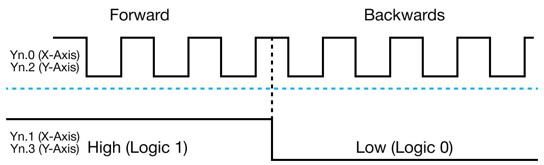
Select Pulse Output
- The select pulse output parameter allows the user to configure and select which pulse output, high or low active, modes to be used according to the pulse input type of the servo or stepper motor drive connected to the positioning module.
- It is possible to configure and adjust the settings on the other side devices.
- If a non-zero value is assigned for this parameter, the pulse signal output is enabled and the signal type, high or low active, can be selected.
- If a zero value is assigned, the pulse signal output is disabled for the specific axis.
High Active
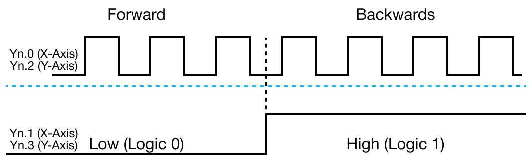
Low Active
Bias Speed
- The bias speed refers to the initial speed of the positioning operation.
- Considering that the torque of a stepper motor is unstable when its initial speed is almost at 0, the initial speed (bias speed) has to be set during early operation in order to facilitate the motor's rotation and to save the positioning time.
- The bias speed should NOT be entered over the selected speed limit value.
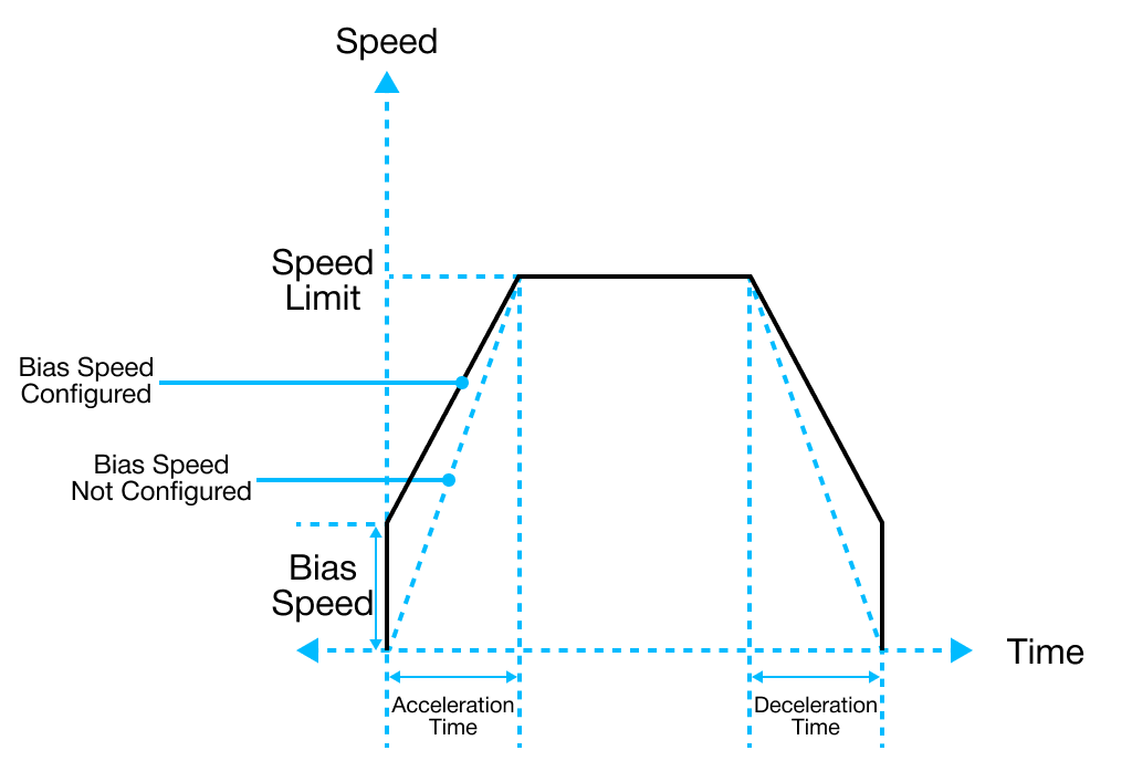
Speed Limit
- The speed limit is the maximum allowable speed that can be set during the positioning operation.
- The positioning operation speed cannot be configured greater than the value set as the speed limit.
Acceleration & Deceleration Time
- Acceleration Time:
- The duration required to reach from 0 (stop) to the maximum speed (speed limit).
- Using the bias would be the time consumed to reach from the bias speed to the speed limit.
- The duration required to reach from 0 (stop) to the maximum speed (speed limit).
- Deceleration Time:
- The duration required to reach from the maximum speed (speed limit) to 0 (stop).
- Using the bias would be the time consumed to reach the bias speed configured in the parameter.
- The duration required to reach from the maximum speed (speed limit) to 0 (stop).
- The actual acceleration or deceleration time can be calculated by the following formula:
- T = V × Ta / Vmax - Vbias
- V: Target speed change
- Ta: Acceleration or deceleration time
- Vmax: Speed limit
- Vbias: Bias speed
- T = V × Ta / Vmax - Vbias
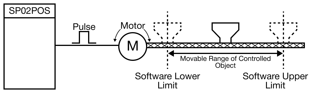
Software Upper & Lower Limit
- The software upper and lower limit is the movable range of a machine in operation.
- This is called the stroke limit.
- It sets the upper and lower limits of the stroke into the software upper and lower limit.
- The software upper and lower limit does not execute positioning if it operates out of the ranges configured in the parameters.
- The range of the software upper and lower limit is checked before starting positioning and also during operation.
- The pulse output stops when an error code (154 & 155) is detected.
- Check for the software limit function is disabled when identical values are assigned for both the upper and lower limits.
Position Indication of the Speed Control
- The position indication of the speed control parameter allows the user to enable or disable the update of the current position address while operations are performed under the speed control.
- The speed control command outputs pulses according to the specified speed and direction until the axis stop signal is entered.
- When the speed control command is executed, how the value of the current coordinates is updated differs depending on the configurations of the position indication of the speed control.
| Position Indication of the Speed Control Parameter | ||
|---|---|---|
| Set Value | Position Address Operation | Description |
| 0 | Do not update | Value is maintained without changing the current coordinates while controlling the speed. |
| 1 | Update Software Upper/Lower Limit Detection | Displays the current coordinate by accelerating or decelerating through the speed control in the last positioning coordinates. Since the current coordinate changes, it is possible to detect the software upper and lower limits. |
| 2 | Clear & Update Software Upper/Lower Limit Detection | After configuring the current coordinates as 0, this function displays the current coordinates as much as the amount of movement. |
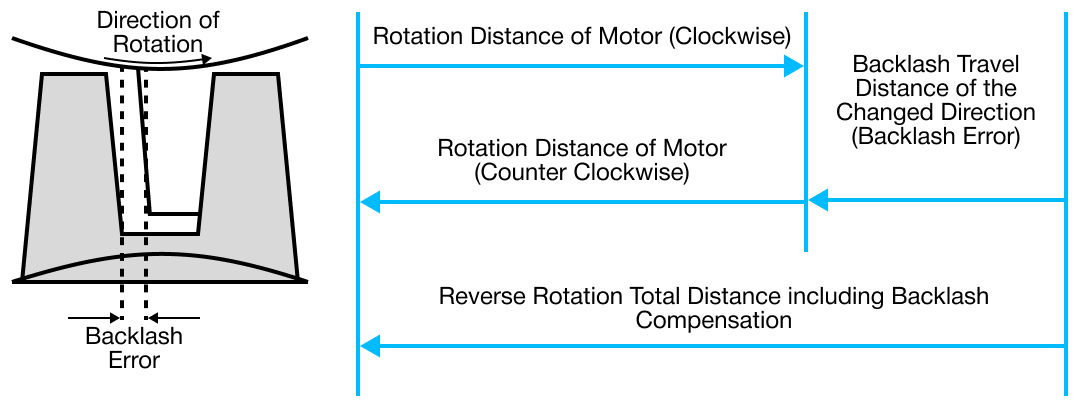
Backlash Compensation
- A loose connection is made on the gear and screws of the motor shaft for the purpose of preventing abrasion.
- Due to this, an error, backlash, occurs during the shifting of a direction.
- The error that occurs due to backlash when moving the machine via gears can be compensated.
- When the backlash compensation amount is configured, the pulse equivalent to the compensation amount will be output each time the direction changes during positioning.
External Upper & Lower Limit input
- To use the external upper limit, (Xn.8 or Xn.B) and the external lower limit (Xn.7 or Xn.A) input signals during operation, this parameter must be set to 1.
- Otherwise, it does not detect the upper and lower limits and the 4 terminals (Xn.7, Xn.8, Xn.A, and Xn.B) will operate as general input contacts.
- The external upper and lower limit input signals operate by B contact.
- The external input signals are detected when switching from ON to OFF.
- The axis stops immediately.
- The external input signals are detected when switching from ON to OFF.
- IMPORTANT: Be cautious when using a stepper motor because the motor may operate out of phase.
JOG Speed Limit
- The JOG operation, a type of manual operation, is driven by a pattern characterized by an acceleration constant speed deceleration.
- This parameter configures the speed for the constant speed phase.
JOG Acceleration & Deceleration Time
- The JOG acceleration and deceleration time parameter configures the period of time for the acceleration and deceleration of the JOG operation.
- The time is assigned by selecting one of the pre-configured values from the Acceleration & Deceleration Time parameter.
- This a value from 0 ~ 3.
- The time is assigned by selecting one of the pre-configured values from the Acceleration & Deceleration Time parameter.
Inching Speed
- The inching operation, a type of manual operation, outputs the specified amount of pulses at the speed configure in this parameter.
- Unlike the JOG operation, which makes it difficult to move to the correct destination because it is driven by the ON and OFF signals of the start contact, the inching operation allows a user to reach the target point by easily setting the desired amount of movement in the inching command.
- The JOG command to move quickly to the vicinity of the work place and then use the POSCTRL-Inching Command for fine movement.
- Or, after writing the desired amount of inching movement at replace this (offset +8) of the operation memory ara, the user can turn ON the JOG and Inching signal to move to the correct location of the work place.
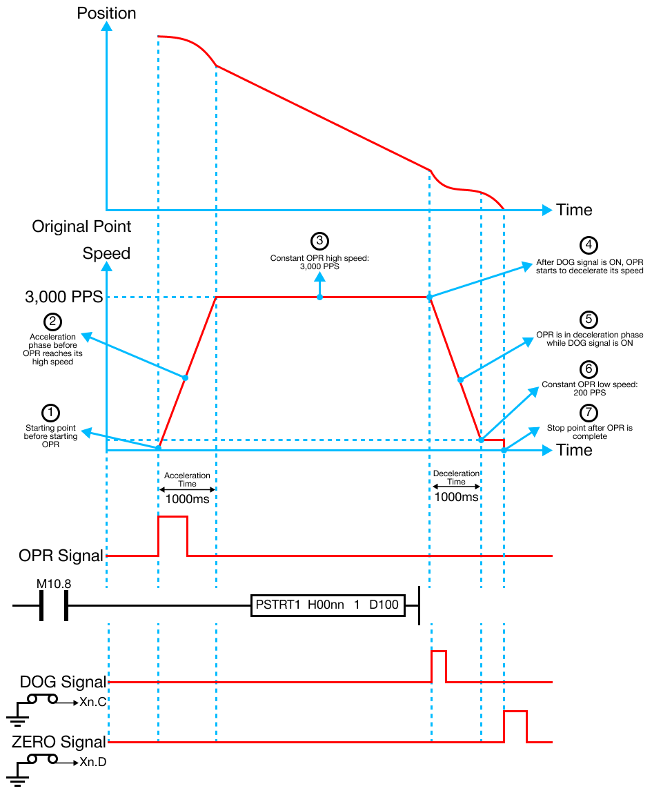
Origin Point Return (OPR) Method
- Origin point return (OR) is executed after power is supplied to confirm the position of the origin, a reference position when executing positioning control.
- The PLC-S provides 3 different OPR Methods:
-
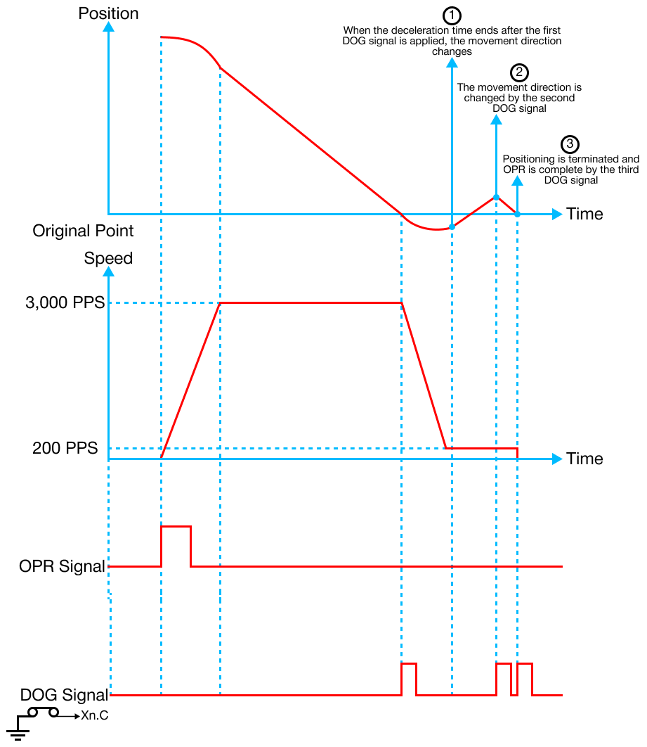
Origin Point (Zero) Detection After Turning DOG OFF
- OPR begins with the OPR high speed in the OPR direction configured under the OPR parameters until the DOG signal is turned ON.
- This will cause the OPR to decelerate with the OPR low speed.
- When the DOD signal is OFF, the first Zero signal is detected, as well as the OPR ending at the same time.
- DOG and Zero signals can be entered by external signals.
- DOG and Zero signals can't be entered in the internal scan program.
- External buttons must be used for DOG and Zero signals.
- DOG and Zero signals can't be entered in the internal scan program.
- OPR begins with the OPR high speed in the OPR direction configured under the OPR parameters until the DOG signal is turned ON.
-
Origin Point (Zero) Detection After Decelerating when DOG Signal is ON
- OPR begins with the OPR high speed in the OPR direction configured under the OPR parameters until the DOG signal is turned ON.
- This will cause the OPR to decelerate with the OPR low speed.
- After the deceleration, the first Zero signal is detected, as well as the OPR ending at the same time.
- OPR begins with the OPR high speed in the OPR direction configured under the OPR parameters until the DOG signal is turned ON.
-
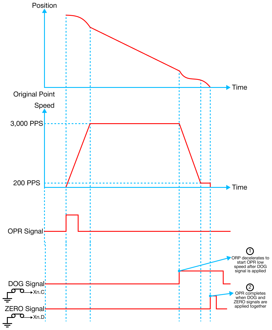
DOG Signal Detection
- OPR begins with the OPR high speed in the OPR direction configured under the OPR parameters until the DOG signal is ON.
- This will cause the OPR to decelerate, stop, and drive in the reverse direction with the OPR low speed.
- When the DOG signal is OFF, OPR decelerates to a stop and then drives in the reverse direction with the OPR low speed.
- When the DOG signal is detected again, the pulse output stops, and OPR is complete.
- OPR begins with the OPR high speed in the OPR direction configured under the OPR parameters until the DOG signal is ON.
Origin Point Return (OPR) Direction
- The origin point return (OPR) direction configures the direction to go to the origin when the OPR command is executed.
Origin Address
- The origin address sets the address used as a reference point for the positioning control (ABS system).
- When OPR is completed, the stop position address is changed to the origin address.
- The origin address is saved as the current positioning address.
Origin Point Return (OPR) High Speed
- The origin point return (OPR) high speed parameter configures the speed for the high speed part of the OPR operation.
- The allowable input range is:
- Bias Speed ≤ OPR low speed ≤ OPR High Speed ≤ Speed Limit
Origin Point Return (OPR) Low Speed
- The origin point return (OPR) low speed parameter configures the speed for the low speed part of the OPR operation.
- The allowable input range is:
- 0 < OPR Low Speed ≤ OPR high speed ≤ Speed Limit
- It is recommended to set the speed limit as low as possible.
- 0 < OPR Low Speed ≤ OPR high speed ≤ Speed Limit
Origin Point Return (OPR) Acceleration & Deceleration Time
- The origin point return (OPR) acceleration and deceleration time parameter specifies the number of the acceleration or deceleration time (1 ~ 4) for the acceleration and deceleration time of the OPR operation.
Dwell Time
- The Dwell time parameter sets the time that the machine dwells after the positioning operation stops (pulse output stop) to the output of the positioning complete signal.