Analog I/O PLC (CM3-SB32) Parameters
Analog I/O
- The Analog I/O parameter is used on PLC CPUs that support embedded analog input and output.
- CM3-SB32MDTF
- CM3-SB32MDCF
- CM3-SB32MDRF
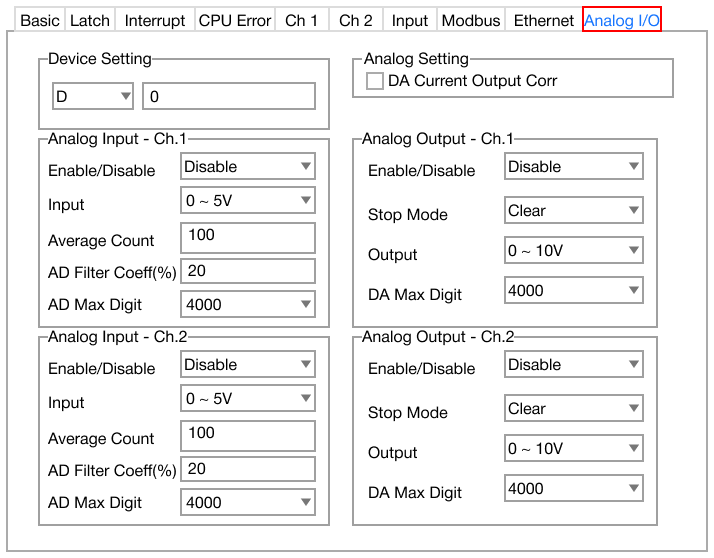
- The Analog I/O PLC parameter contains the following sections:
- For more information on how to use analog input/output on an embedded PLC CPU, refer here.
Device Setting

- Data Register:
- This is the data register type for analog input/output.
- Number:
- This is the starting data register number for analog input/output.
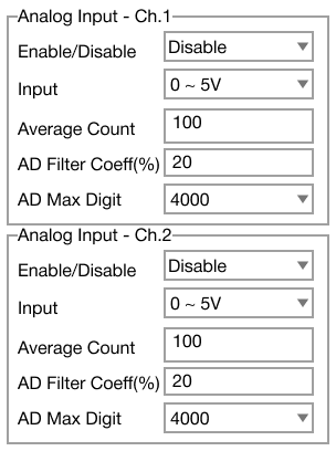
- Enable/Disable:
- Enables or disables analog input for channel 1 or channel 2.
- Input:
- Specifies the analog input type:
- Voltage:
- 0V ~ +5V
- 0V ~ +10V
- +1V ~ +5V
- +1V ~ +10V
- Current:
- Average Count:
- Used for enabling the moving window filtering feature.
- The value range is 0 ~ 255.
- 0 disables the moving window filtering feature.
- AD Filter Coeff(%):
- This sets the AD filter coefficient percentage.
- AD Max Digit:
- This is the maximum digital value from the analog input.
- The values are 4,000 or 16,000(SW).
- 16,000 requires the DIP Switch to be enabled.
Analog Output Channel 1 & Channel 2
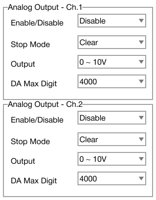
- Enable/Disable:
- Enables or disables analog output for channel 1 or channel 2.
- Stop Mode:
- Determines if the analog value is maintained or cleared when the PLC is in STOP mode.
- The options are:
- Hold: maintain the value
- Clear: clear the value
- Output:
- Specifies the analog output type:
- DA Max Digit:
- This is the maximum digital value from the analog output.
- The values are 4,000 or 16,000(SW).
- 16,000 requires the DIP Switch to be enabled.