Ethernet PLC Parameters
Ethernet
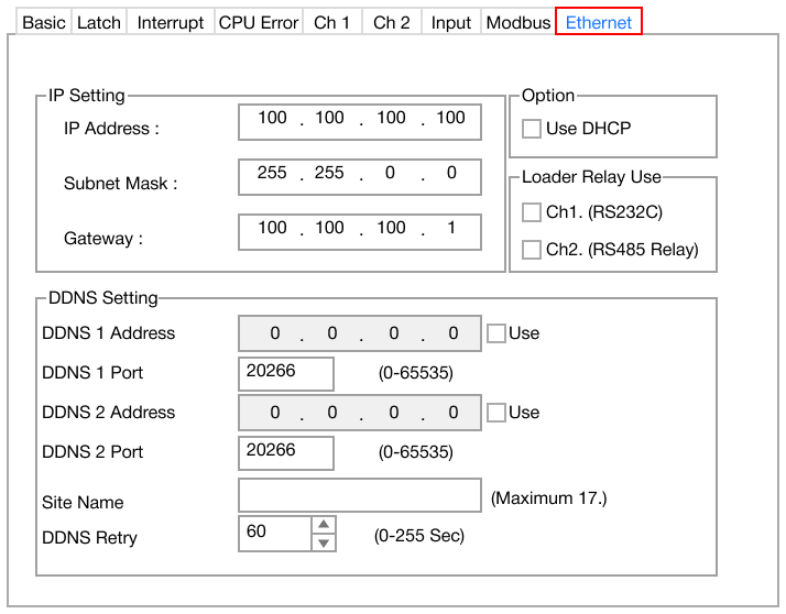
- The Ethernet parameter is used for 802.3 network communication with the PLC.
- The Ethernet PLC parameter contains the following sections:
IMPORTANT: The subnet mask and gateway must match the network of the computer to communicate with the PLC.
IP Setting

- IP Address:
- This is PLC's unique address on the network.
- Default: 100.100.100.100
- This is PLC's unique address on the network.
- Subnet Mask:
- This is the range of IP addresses within a network.
- Default: 255.255.0.0
- This is the range of IP addresses within a network.
- Gateway:
- This specifies the address of the network's gateway (router or central device) that provides access to other networks.
- Default: 100.100.100.1
- This specifies the address of the network's gateway (router or central device) that provides access to other networks.
DDNS Setting
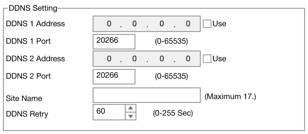
- Dynamic Domain Name System, DDNS, maps a domain name to a dynamic IP address.
- DDNS 1 Address:
- Primary DDNS server IP address.
- Default: 0.0.0.0
- Primary DDNS server IP address.
- DDNS 1 Port:
- Specifies the port for the primary DDNS server.
- Default: 20266
- Range: 0 ~ 65,535
- Specifies the port for the primary DDNS server.
- DDNS 2 Address:
- Secondary DDNS server IP address.
- Default: 0.0.0.0
- Secondary DDNS server IP address.
- DDNS 2 Port:
- Specifies the port for the secondary DDNS server.
- Default: 20266
- Range: 0 ~ 65,535
- Specifies the port for the secondary DDNS server.
- Site Name:
- A unique website identifier associated with this device.
- Maximum 17 characters
- A unique website identifier associated with this device.
- DDNS Retry:
- Retry interval, in seconds, if the device fails to connect to the DDNS server.
- Default: 60 seconds
- Range: 0s ~ 255s
- Retry interval, in seconds, if the device fails to connect to the DDNS server.
Option

- Use DHCP:
- If checked, the PLC will use the dynamic host control protocol, DHCP, to assign an IP address.
Loader Relay Use

- Ch1. (RS232C):
- If checked, channel 1 is enabled for RS-232(C) relay.
- Ch2. (RS485 Relay):
- If checked, channel 2 is enabled for RS-422/RS-485 relay.
Wiring
- This interface is satisfied with the IEEE802.3 standard for 10BaseT/100BaseTX.
- The cable and allocation pin number of RJ45 as shown below:
| RJ45 Connection | |
|---|---|
| RJ45 Connector | RJ45 Jack |
 |  |
Straight-through Cable (Host ↔ Switch)
- The PLC must be connected to an Ethernet switch/hub if using a standard straight-through Ethernet cable.
| Straight-through Cable Wiring | |||||
|---|---|---|---|---|---|
| RJ45 Jack End 1 | RJ45 Jack End 2 | ||||
| Cable | Number | Color | Color | Number | Cable |
 | 1 | Orange/White | Orange/White | 1 | |
| 2 | Orange | Orange | 2 | ||
| 3 | Green/White | Green/White | 3 | ||
| 4 | Blue | Blue | 4 | ||
| 5 | Blue/White | Blue/White | 5 | ||
| 6 | Green | Green | 6 | ||
| 7 | Brown/White | Brown/White | 7 | ||
| 8 | Brown | Brown | 8 | ||
Crossover Cable (Host ↔ Host)
- If the PLC is directly connected to another PLC or HMI, a crossover Ethernet cable must be used.
| Crossover Cable Wiring | |||||
|---|---|---|---|---|---|
| RJ45 Jack End 1 | RJ45 Jack End 2 | ||||
| Cable | Number | Color | Color | Number | Cable |
| 1 | Orange/White | Green/White | 1 |  |
| 2 | Orange | Green | 2 | ||
| 3 | Green/White | Orange/White | 3 | ||
| 4 | Blue | Blue | 4 | ||
| 5 | Blue/White | Blue/White | 5 | ||
| 6 | Green | Orange | 6 | ||
| 7 | Brown/White | Brown/White | 7 | ||
| 8 | Brown | Brown | 8 | ||