CM3 High-Speed Counter Module Major Functions
Counter Input Mode
| Counter Input Mode | |||
|---|---|---|---|
| Input Method | A-Phase Input | B-Phase Input | Up/Down Counting |
| 1-Phase 2-Multiplication | Direction Input (Low Active) | Pulse Input | A-Phase is low: Up count A-Phase is high: Down count |
| 1-Phase 2-Multiplication | Direction Input (High Active) | Pulse Input | A-Phase is low: Down count A-Phase is high: Up count |
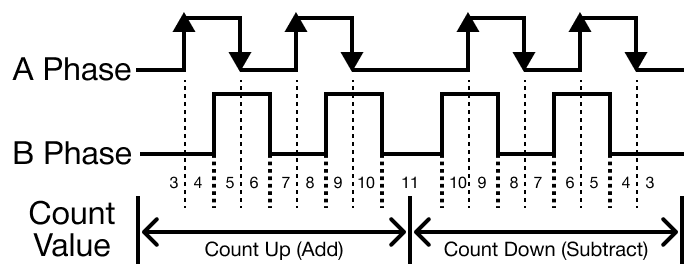
| 2-Phase 2-Multiplication | A-Phase Pulse Input | B-Phase Pulse Input | A precedes B: Up count B precedes A: Down count |
| 2-Phase 4-Multiplication | A-Phase Pulse Input | B-Phase Pulse Input | A precedes B: Up count B precedes A: Down count |
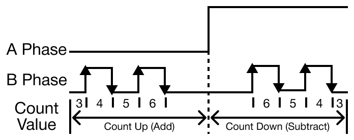
1-Phase 2-Multiplication (Low Active)
- The increase or decrease in the direction of the count is dependent on the A-Phase input state.
- The 1-Phase 2 Multiplication input method is not recommended for a system that requires a frequent change in direction because the count value is made by the A-Phase signal.
- For a precise measurement, 2-Phase 2-Multiplication or 2-Phase 4-Multiplication should be used.
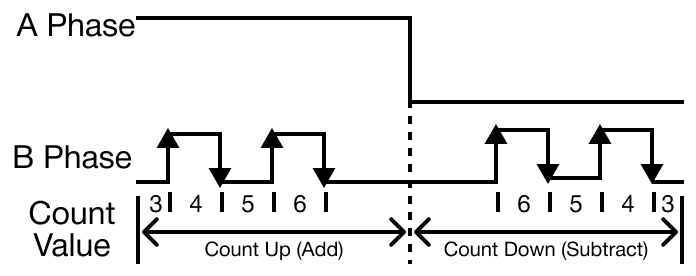
1-Phase 2-Multiplication (High Active)
- The increase or decrease in the direction of the count is dependent on the A-Phase input state.
- The 1-Phase 2 Multiplication input method is not recommended for a system that requires a frequent change in direction because the count value is made by the A-Phase signal.
- For a precise measurement, 2-Phase 2-Multiplication or 2-Phase 4-Multiplication should be used.
2-Phase 2-Multiplication
- The count is processed when the A-Phase input signal changes.
- The increase or decrease of in the direction of the count is dependent on the state of the B-Phase signal at the moment the A-Phase signal changes.
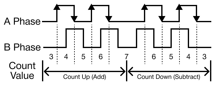
2-Phase 4-Multiplication
- The count is processed each time the input signals for both A-Phase and B-Phase change.
- The direction of the changing signal and state of the opposing signal determine whether to increment or decrement the count.
Counter Types
The CM3-SP02HSC and CM3-SP02HSD have two counter types.
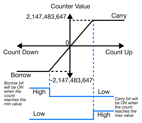
Linear Counter
- If the count value reaches the maximum value, 2,147,483,647, while incrementing, carry occurs.
- If the count value reaches the minimum value, -2,147,483,648, while decrementing, borrow occurs.
- If carry occurs, counting stops and will no longer increment.
- Decrementing is still possible.
- If borrow occurs, counting stops and will no longer decrement.
- Incrementing is still possible.
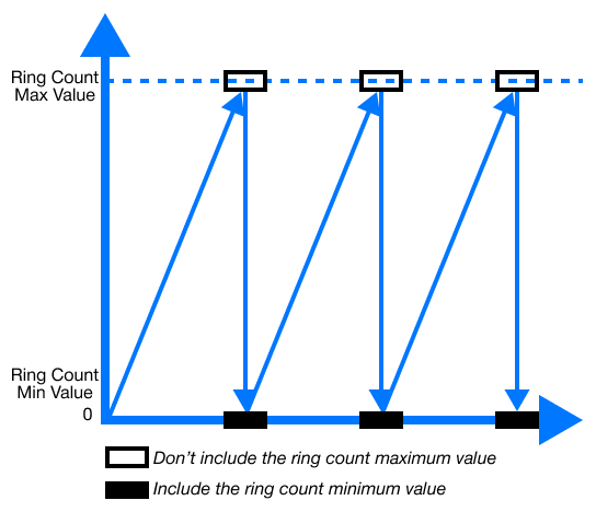
Ring Counter
- The range for ring counting is from 0 ~ user-defined maximum value.
- Ring Increment Count:
- If the count value exceeds the user-defined maximum value while incrementing, carry occurs.
- The count operation will continue from 0.
- The carry flag is maintained until the reverse pulse input is entered.
- If the count value exceeds the user-defined maximum value while incrementing, carry occurs.
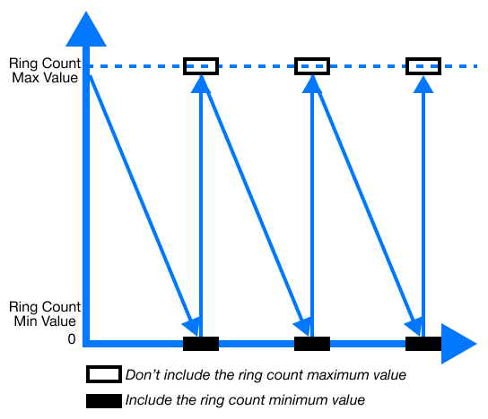
- Ring Decrement Count:
- If the count value reaches 0 while decrementing, borrow occurs.
- The count operation will continue from the user-defined maximum value.
- The borrow flag is maintained until the reverse pulse input is entered.
- If the count value reaches 0 while decrementing, borrow occurs.
If the current count value exceeds the user-defined range when setting up the ring count, it is considered as a user error.
- If an error occurs, it operates the linear count.
Compared Output
- There is 1 compared output function for each channel.
- There are 7 compared output conditions, or modes, available with combinations of >, =, and <.
- In order to use the compared output signal, Enable Compare Output (Y) must be selected in the Channel Configuration window of the special program titled HSC for PLC-S.
- A user can output an external signal by specifying Yn.0 ~ Yn.7 as the compared output signals.
- n in Yn.0 ~ Yn.7 is the CM3-SP02HSC or CM3-SP02HSD's position on the chassis.
| Compared Outputs | |
|---|---|
| Code | Compared Output Conditions |
| 0 | Current count < Compared value |
| 1 | Current count ≤ Compared value |
| 2 | Current count = Compared value |
| 3 | Current count ≥ Compared value |
| 4 | Current count > Compared value |
| 5 | Compared value 1 ≤ Current count ≤ Compared value 2 (inclusive) |
| 6 | Current count ≤ Compared value 1 Current count ≥ Compared value 2 (Exclusive) |
Counter Latch
- By latching, the counter value is neither cleared nor initialized when the power changes from OFF to ON, and the mode changes.
- The count continues from the previous value.
- If a user wants to initialize the current count in this case, the user must use the internal or external preset function.
- The count continues from the previous value.
- The latch counter is activated when Latch Count is selected in the special program HSC for PLC-S.
Input Pulse Count Per Unit Time
- The input pulse count per unit time function counts the number of input pulses for a specified time.
- To use this function, Unit Time must be set to a value greater than 0.
- The measured values are updated for each unit time configuration period.
- To use this function, Unit Time must be set to a value greater than 0.
- Unit time (milliseconds):
- If 0 seconds is selected, this function and RPM/PPS cannot be operated.
- Pulse per 1 Cycle:
- This is used for the rotations per minute (RPM) function.
- If the parameter is configured to 0, the RPM function will not operate.
- The counter works in the pulses per second (PPS) unit regardless of other parameter values.
- If the parameter is configured to 0, the RPM function will not operate.
- This is used for the rotations per minute (RPM) function.
- The built-in high-speed counter of the PLC-S (mini modular and brick series) counts the input pulse speed through the above parameters.
- The unit time, pulses per second (PPS), or rotations per minute (RPM) parameters can be selected.
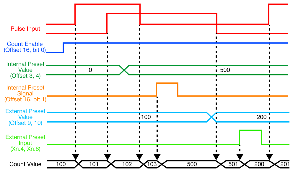
Preset Function
- The preset function changes the current counter value into the configured preset value.
- There is an internal and external preset.
- The external preset is fixed as an input contact point for each channel.
- It is activated by a sent signal.
- The external preset is fixed as an input contact point for each channel.
- The external signal for channel 1 (X0004) and channel 2 (X0006) must be used.
- Preset operation begins when the command or input signal is switched from OFF to ON.