Device Communication Introduction
Device Communication Description
CIMON’s HMIs can connect with PLCs and other HMIs to display relevant information for the project. HMIs can connect with other devices via ethernet and USB mini as well. With these tools, users can display information from HMIs and other PLCs to help display a project more efficiently and easier to read than from reading from a PLC.
Device Communication Designer Functionalities
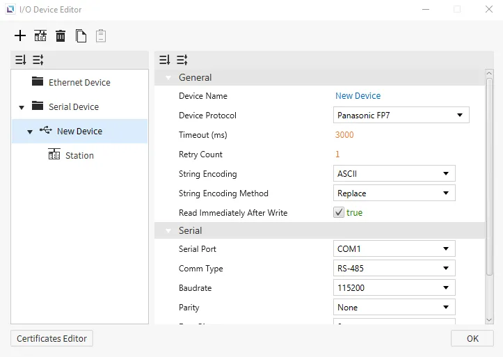
I/O Device Editor
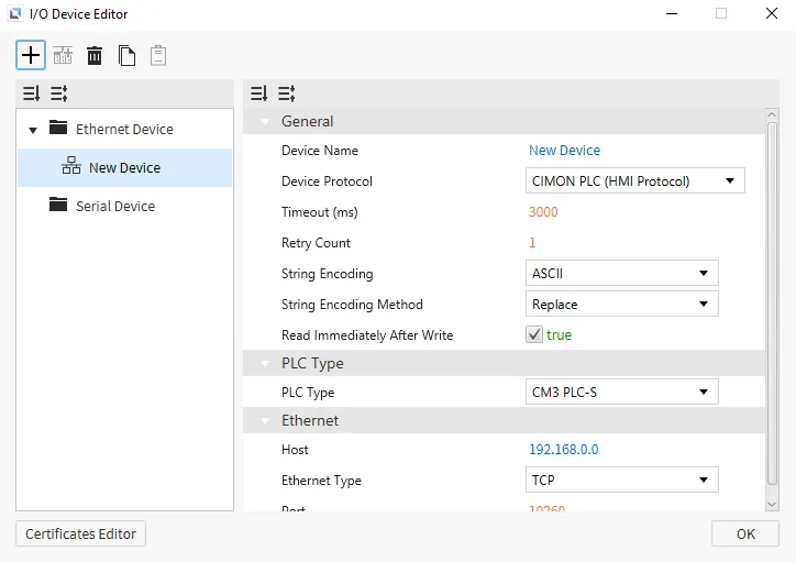
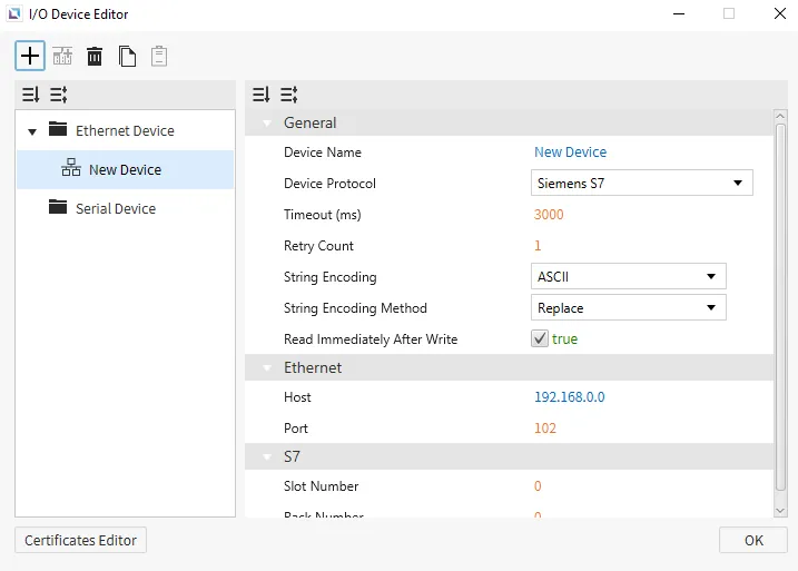
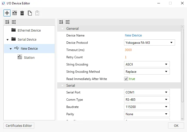
To access I/O Device Editor, go to Tools > I/O Device Editor, or click on the Open I/O Device Editor… on the toolbar to open it. To create a new device, click the + icon to open the Add New I/O Device screen. Users can select the ethernet or serial Connection Type for that specific device. Users can also set the Device Type, which will open a dropdown of specific devices that Canvas supports connecting to. Once selected, the I/O Device will be created with default settings.
Ethernet Device
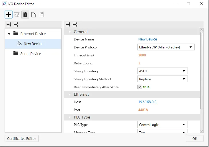
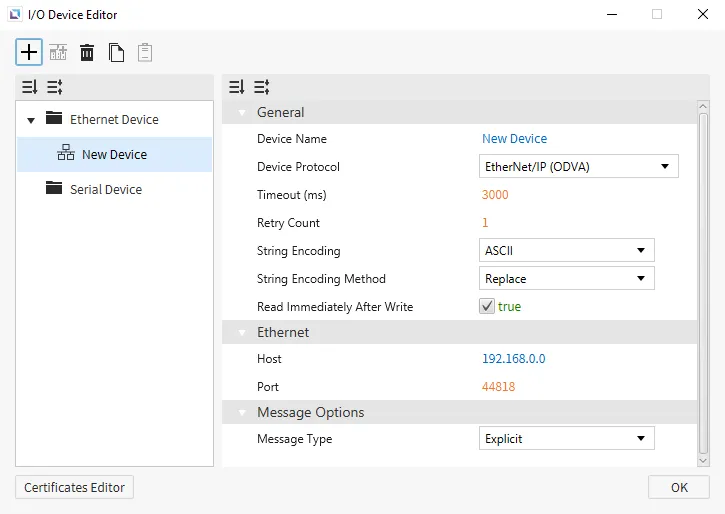
Ethernet devices are used when the connection to another device is via an Ethernet connection. Users must input the IP of the device they are connecting to, the Ethernet Type, and the Port. Depending on the selected protocol, users can also set the PLC Type. Users can also select the String Encoding and the String Encoding Method. Users can also change settings such as the Timeout time and the Retry Count. Users will also be able to change the name of the Device and the Protocol of the device as well. Users can use a different protocol to suit the use case of a specific project; the available protocols are listed below.

Allen-Bradley Ethernet/IP
Canvas supports Allen-Bradleys Ethernet/IP as a way to connect with other devices that support this protocol. Users will be able to select an Allen Bradley PLC Type, the Message Type, and a toggle to Use Multiple Service
ControlLogix/CompactLogix SLC Mapping
Address Structure: [Symbol][File No.]:[Element No.]/[Bit No.]
| Name | Symbol | Digital | Analog |
|---|---|---|---|
| BOOL (BOOL) | B | B0:0/0 - B999:999/31 | B3:0 - B3:255 |
| INT (WORD) | N | N0:0/0 - N999:999/15 | N7:0 - N7:255 |
| REAL (FLOAT) | F | F0:0/0 - F999:999/31 | F8:0 - F8:255 |
-
Based on the file type, element no. 256 is not supported. Error code from PLC will be received when unsupported settings are downloaded. Change the PLC settings in this case.
-
Only the device has Word Tag.
-
The BOOL and REAL devices can be used for digital or 32-bit analog tags.
MicroLogix
- PCCC Mapping
Address Structure: [Symbol][File No.]:[Element No.]/[Bit No.]
| Memory Area | Symbol | Analog | Digital | Address Notation | Access |
|---|---|---|---|---|---|
| Output | O | O:0.0 - O:0.30 | O:0.0/0 - O:0.30/15 | Decimal | R/W |
| Input | I | I:1.0 - I:1.30 | I:1.0/0 - I:1.30/15 | Decimal | R |
| Binary | B | B3:0 - B3:255 | B3:0/0 - B3:255/15 | Decimal | R/W |
| Integer | N | N7:0 - N7:255 | N7:0/0 - N7:255/15 | Decimal | R/W |
| Float | F | F8:0 - F8:255 | Decimal | R/W | |
| Status | S | S:0 - S:163 | S:0/0 - S:163/15 | Decimal | R |
Supported Symbols
MicroLogix
| Name | Symbol | Bit Range | Word Range |
|---|---|---|---|
| Output | O | O:0.0/0 – O:30.255/15 | O:0.0 – O:30.255 |
| Input | I | I:0.0/0 – I:30.255/15 | I:0.0 – I:30.255 |
| Status | S | S:0/0 – S:163/15 | S:0 – S:163 |
| Binary | B | B3:0/0 – B3:255/15 B9:0/0 – B255:255/15 | B3:0/0 – B3:255/15 B9:0/0 – B255:255/15 |
| Integer | N | N7:0/0 – N7:255/15 N9:0/0 – N255:255/15 | N7:0 – N7:255 N9:0 – N255:255 |
| Float | F | - | F8:0 – F255:255 Float only. |
| String | ST | - | ST9:0 – ST255:255 |
| Long | L | - | L9:0 – L255:255 UINT32, INT32 only. |
| Timer | T | T4:0.0/0 – T4:255.2/15 Txx:nn .0/15 Txx:nn .0/14 Txx:nn .0/13 | T4:0.0 – T4:255.2 T9:0.0 - T255:255.2 Txx:nn .1 = Preset Value (PRE) Txx:nn .2 = Accumulated Value (ACC) |
| Counter | C | C5:0.0/0 – C5:255.2/15 Cxx:nn .0/15 Cxx:nn .0/14 Cxx:nn .0/13 Cxx:nn .0/12 Cxx:nn .0/11 Cxx:nn .0/10 | C5:0.0 – C5:255.2 C9:0.0 – C255:255.2 Cxx:nn .1 = Preset (PRE) Cxx:nn .2 Accumulated Value (ACC) |
| Control | R | R6:0.0/0 – R6:255.2/15 Rxx:nn .0/15 Rxx:nn .0/14 Rxx:nn .0/13 Rxx:nn .0/12 Rxx:nn .0/11 Rxx:nn .0/10 Rxx:nn .0/9 Rxx:nn .0/8 | R6:0.0 – R6:255.2 R9:0.0 – R255:255.2 Rxx:nn .1 = Length value Rxx:nn .2 = position value |
Communication Cable Wiring
This interface is satisfied with standard IEEE802.3 about the 10BaseT/100BaseTX. You can configure the cable and allocation pin number of RJ45 as shown below.
| RJ45 Connector | RJ45 Jack |
|---|---|
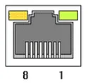 | 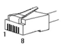 |
Direct Cable: Host <-> HUB
| Cable | No. | Color | Color | No. | Cable |
|---|---|---|---|---|---|
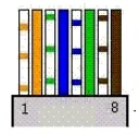 | 1 | Orange/White | Orange/White | 1 | 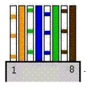 |
| 2 | Orange | Orange | 2 | ||
| 3 | Green/White | Green/White | 3 | ||
| 4 | Blue | Blue | 4 | ||
| 5 | Blue/White | Blue/White | 5 | ||
| 6 | Green | Green | 6 | ||
| 7 | Brown/White | Brown/White | 7 | ||
| 8 | Brown | Brown | 8 |
Crossover Cable: Host <-> Host
| Cable | No. | Color | Color | No. | Cable |
|---|---|---|---|---|---|
| 1 | Orange/White | Green/White | 1 | 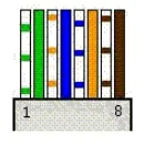 |
| 2 | Orange | Green | 2 | ||
| 3 | Green/White | Orange/White | 3 | ||
| 4 | Blue | Blue | 4 | ||
| 5 | Blue/White | Blue/White | 5 | ||
| 6 | Green | Orange | 6 | ||
| 7 | Brown/White | Brown/White | 7 | ||
| 8 | Brown | Brown | 8 |
CIMON PLC (HMI Protocol)
CIMON PLC (HMI Protocol) is the default protocol for Canvas. This protocol is the basic HMI protocol to connect with other CIMON devices. Users can select the CIMON PLC Type that they are working with. There are no additional options for any of the CIMON PLCs; the settings will remain the same across all CIMON PLCs.
CIMON PLC connections with ethernet will require a UDP Ethernet type to function properly.
All CIMON PLCs
Address Structure: [Device][Element No.]
| Name | Symbol | Digital | Analog |
|---|---|---|---|
| BOOL (BOOL) | M | M0000 - M999F | M0000 - M9990 |
| INT (WORD) | D | D00000.0 - D31999.F | D00000 - D31999 |
All CIMON CPUs support reading D bits; however, the CM1-UPnF and PLC-S Pro only support writing to D bits.
Supported Devices
| Area | Device | Bit Range | Word Range | Access |
|---|---|---|---|---|
| Input | X | X0000 - X511F | X0000 - X5110 | R/W |
| Output | Y | Y0000 - Y511F | Y0000 - Y5110 | R/W |
| Binary | M | M0000 - M999F | M0000 - M9990 | R/W |
| Binary | L | L0000 - L999F | L0000 - L9990 | R/W |
| Non-Volatile Binary | K | K0000 - K999F | K0000 - K9990 | R/W |
| Status | F | F0000 - F127F | F0000 - F1270 | R |
| Timer | T | T0000 - T4095 | - | R/W |
| Counter | C | C0000 - C4095 | - | R/W |
| Control | S | S00 - S99 | - | |
| Integer | D | - | D00000 - D31999 | R/W |
| Index | R | - | - | |
| Timer - Current Count | TC | - | TC0000 - TC4099 | R/W |
| Timer - Timer Set | TS | - | TS0000 - TS4099 | R/W |
| Counter - Current Count | CC | - | CC0000 - CC4099 | R/W |
| Counter - Count Set | CS | - | CS0000 - CS4099 | R/W |
| Integer | Z | - | Z0000 - Z1023 |
Communication Cable Wiring
This interface is satisfied with standard IEEE802.3 about the 10BaseT/100BaseTX. You can configure the cable and allocation pin number of RJ45 as shown below.
| RJ45 Connector | RJ45 Jack |
|---|---|
| |
Direct Cable: Host <-> HUB
| Cable | No. | Color | Color | No. | Cable |
|---|---|---|---|---|---|
| 1 | Orange/White | Orange/White | 1 | |
| 2 | Orange | Orange | 2 | ||
| 3 | Green/White | Green/White | 3 | ||
| 4 | Blue | Blue | 4 | ||
| 5 | Blue/White | Blue/White | 5 | ||
| 6 | Green | Green | 6 | ||
| 7 | Brown/White | Brown/White | 7 | ||
| 8 | Brown | Brown | 8 |
Crossover Cable: Host <-> Host
| Cable | No. | Color | Color | No. | Cable |
|---|---|---|---|---|---|
| 1 | Orange/White | Green/White | 1 | |
| 2 | Orange | Green | 2 | ||
| 3 | Green/White | Orange/White | 3 | ||
| 4 | Blue | Blue | 4 | ||
| 5 | Blue/White | Blue/White | 5 | ||
| 6 | Green | Orange | 6 | ||
| 7 | Brown/White | Brown/White | 7 | ||
| 8 | Brown | Brown | 8 |
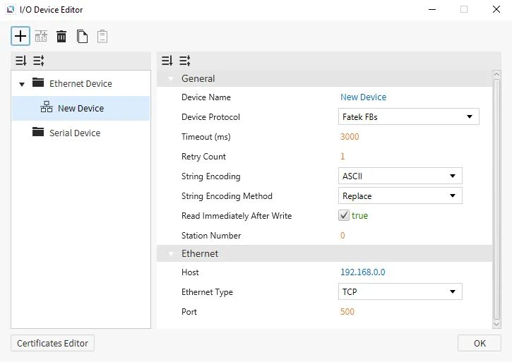
Fatek FBS
Canvas supports Fatek FBS as a way to connect with other devices that support this protocol. This protocol will work in conjunction with any Fatek PLCs. There are no specific settings that this option will bring up if selected.
Supported Symbols
| Area | Symbol | Bit Range | Word Range (16-bit) | Word Range (32-bit) | Access |
|---|---|---|---|---|---|
| Input | X, WX, DWX | X0000 - X9999 | WX0000 - WX9984 | DWX0000 - DWX9968 | R |
| Output | Y, WY, DWY | Y0000 - Y9999 | WY0000 - WY9984 | DWY0000 - DWY9968 | R/W |
| Binary | M, WM, DWM | M0000 - M9999 | WM0000 - WM9984 | DWM0000 - DWM9968 | R/W |
| Timer | T, WT, DWT | T0000 - T9999 | WT0000 - WT9984 | DWT0000 - DWT9968 | R/W |
| Control | S, WS, DWS | S0000 - S9999 | WS0000 - WS9984 | DWS0000 - DWS9968 | R/W |
| Timer Register | RT, DRT | - | RT0000 - RT9999 | DRT0000 - DRT9998 | R/W |
| Counter Register | RC, DRC | - | RC0000 - RC9999 | DRC0000 - DRC9998 | R/W |
| Control | R, DR | - | R00000 - R65535 | DR00000 - DR65534 | R/W |
| Data Register | D, DD | - | D00000 - D65535 | DD00000 - DD65534 | R/W |
| File Register | F, DF | - | F00000 - F65535 | DF00000 - DF65534 | R/W |
Communication Cable Wiring
This interface is satisfied with standard IEEE802.3 about the 10BaseT/100BaseTX. You can configure the cable and allocation pin number of RJ45 as shown below.
| RJ45 Connector | RJ45 Jack |
|---|---|
| |
Direct Cable: Host <-> HUB
| Cable | No. | Color | Color | No. | Cable |
|---|---|---|---|---|---|
| 1 | Orange/White | Orange/White | 1 | |
| 2 | Orange | Orange | 2 | ||
| 3 | Green/White | Green/White | 3 | ||
| 4 | Blue | Blue | 4 | ||
| 5 | Blue/White | Blue/White | 5 | ||
| 6 | Green | Green | 6 | ||
| 7 | Brown/White | Brown/White | 7 | ||
| 8 | Brown | Brown | 8 |
Crossover Cable: Host <-> Host
| Cable | No. | Color | Color | No. | Cable |
|---|---|---|---|---|---|
| 1 | Orange/White | Green/White | 1 | |
| 2 | Orange | Green | 2 | ||
| 3 | Green/White | Orange/White | 3 | ||
| 4 | Blue | Blue | 4 | ||
| 5 | Blue/White | Blue/White | 5 | ||
| 6 | Green | Orange | 6 | ||
| 7 | Brown/White | Brown/White | 7 | ||
| 8 | Brown | Brown | 8 |
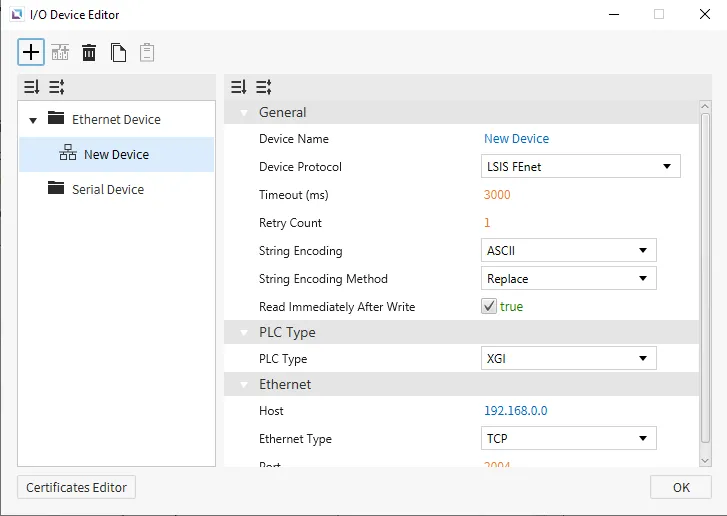
LSIS FEnet
Canvas supports LSIS FEnet as a way to connect with other devices that support this protocol. Users can select an LSIS PLC Type within the settings to suit specific configurations better.
Supported Symbols
XGK (XGK-CPU* / XBM / XBC)
| Name | Symbol | Bit Range | Word Range | Access |
|---|---|---|---|---|
| Input/Output | P | P00000 - P2047F | P0000 - P2047 | R/W |
| Binary | M | M00000 - M2047F | M0000 - M2047 | R/W |
| Binary | L | L000000 - L11263F | L00000 - L11263 | R/W |
| Non-Volatile Binary | K | K00000 - K4095F | K0000 - K4095 | R/W If the CPU is XGK, the bit range is "K00000 - K2047F" and the word range is "K0000 - K2047". |
| Status | F | F00000 - F2047F | F0000 - F2047 | R |
| Timer | T | T0000 - T2047 | - | R/W |
| Counter | C | C0000 - C2047 | - | R/W |
| Control | S | - | - | - |
| Integer | D | - | D00000 - D32767 | R/W |
| Index | R | - | R00000 - R32767 | R/W XBM does not support the R and ZR. XBC supports only R. (R and ZR are the same device in the XBC.) |
| Index | ZR | - | ZR00000 - ZR65535 | R/W XBM does not support the R and ZR. XBC supports only R. (R and ZR are the same device in the XBC.) |
| Timer - Current Count | T | - | T0000 - T2047 | R/W |
| Counter - Current Count | C | - | C0000 - C2047 | R/W |
| Comm. Data Register | N | - | N00000 - N21503 | R/W |
| Integer | Z | - | Z000 - Z127 | R/W |
XGK (XGK-CPUSN / XGK-CPUHN / XGK-CPUUN)
| Name | Symbol | Bit Range | Word Range | Access |
|---|---|---|---|---|
| Input/Output | P | P00000 - P4095F | P0000 - P4095 | R/W |
| Binary | M | M00000 - M4095F | M0000 - M4095 | R/W |
| Binary | L | L000000 - L11263F | L00000 - L11263 | R/W |
| Non-Volatile Binary | K | K00000 - K4095F | K0000 - K4095 | R/W |
| Status | F | F00000 - F4095F | F0000 - F4095 | R |
| Timer | T | T0000 - T8191 | - | R/W |
| Counter | C | C0000 - C4095 | - | R/W |
| Control | S | - | S000 - S255 | R/W |
| Integer | D | - | D000000 - D524287 | R/W If the CPU is XGK-CPUSN, the word range is "D000000 - D262143". |
| Index | R | - | R00000 - R32767 | R/W |
| Index | ZR | - | ZR000000 - ZR524287 | R/W |
| Timer - Current Count | T | - | T0000 - T8191 | R/W |
| Counter - Current Count | C | - | C0000 - C4095 | R/W |
| Comm. Data Register | N | - | N00000 - N21503 | R/W |
| Integer | Z | - | Z000 - Z255 | R/W |
| Special Module Register | U | - | U00.00 - U7F.31 | R/W If the CPU is XGK-CPUSN, the word range is "U00.00 - U3F.31". |
XGI
| Name | Symbol | Bit Range | Byte Range | Word Range | DWord Range | QWord Range | Access |
|---|---|---|---|---|---|---|---|
| Input Points | I | %IX000.00.00 - %IX127.15.63 | %IB000.00.0 - %IB127.15.7 | %IW000.00.0 - %IW127.15.3 | %ID000.00.0 - %ID127.15.1 | %IL000.00.0 - %IL127.15.0 | R/W |
| Output Points | Q | %QX000.00.00 - %QX127.15.63 | %QB000.00.00 - %QB127.15.7 | %QW000.00.00 - %QW127.15.3 | %QD000.00.0 - %QD127.15.1 | %QL000.00.0 - %QL127.15.0 | R/W |
| Automatic Variable | A | %AX0000000 - %AX8388607 | %AB0000000 - %AB1048575 | %AW000000 - %AW524287 | %AD000000 - %AD262143 | %AL000000 - %AL131071 | R/W |
| Direct Variable | M | %MX0000000 - %MX4194303 | %MB0000000 - %MB524287 | %MW000000 - %MW262143 | %MD000000 - %MD131071 | %ML00000 - %ML65535 | R/W |
| Direct Variable | R | %RX0000000 - %RX524287 | %RB00000 - %RB65535 | %RW00000 - %RW32767 | %RD00000 - %RW16383 | %RL0000 - %RL8191 | R/W |
| Direct Variable | W | %WX0000000 - %WX8388607 | %WB0000000 - %WB1048575 | %WW000000 - %WW524287 | %WD000000 - %WD262143 | %WL000000 - %WL131071 | R/W |
| System Flag | F | %FX00000 - %FX65535 | %FB0000 - %FB8191 | %FW0000 - %FW4095 | %FD0000 - %FD2047 | %FL0000 - %FL1023 | R |
| PID Flag | K | %KX000000 - %KX134399 | %KB00000 - %KB16799 | %KW0000 - %KW8399 | %KD0000 - %KD4299 | %KL0000 - %KL2199 | R/W |
| HS Link Flag | L | %LX000000 - %LX180223 | %LB00000 - %LB22527 | %LW00000 - %LW11263 | %LD0000 - %LD5631 | %LL0000 - %LL2815 | R/W |
| Analog Refresh Flag | U | %UX0.00.000 - %UX7.15.511 | %UB0.00.000 - %UB7.15.63 | %UW0.00.000 - %UW7.15.31 | %UD0.00.000 - %UD7.15.15 | %UL0.00.000 - %UL7.15.7 | R/W |
| P2P Parameters Flag | N | %NX000000 - %NX401407 | %NB00000 - %NB50175 | %NW00000 - %NW25087 | %ND00000 - %ND12543 | %NL0000 - %NL6271 | R/W |
Communication Cable Wiring
This interface is satisfied with standard IEEE802.3 about the 10BaseT/100BaseTX. You can configure the cable and allocation pin number of RJ45 as shown below.
| RJ45 Connector | RJ45 Jack |
|---|---|
| |
Direct Cable: Host <-> HUB
| Cable | No. | Color | Color | No. | Cable |
|---|---|---|---|---|---|
| 1 | Orange/White | Orange/White | 1 | |
| 2 | Orange | Orange | 2 | ||
| 3 | Green/White | Green/White | 3 | ||
| 4 | Blue | Blue | 4 | ||
| 5 | Blue/White | Blue/White | 5 | ||
| 6 | Green | Green | 6 | ||
| 7 | Brown/White | Brown/White | 7 | ||
| 8 | Brown | Brown | 8 |
Crossover Cable: Host <-> Host
| Cable | No. | Color | Color | No. | Cable |
|---|---|---|---|---|---|
| 1 | Orange/White | Green/White | 1 | |
| 2 | Orange | Green | 2 | ||
| 3 | Green/White | Orange/White | 3 | ||
| 4 | Blue | Blue | 4 | ||
| 5 | Blue/White | Blue/White | 5 | ||
| 6 | Green | Orange | 6 | ||
| 7 | Brown/White | Brown/White | 7 | ||
| 8 | Brown | Brown | 8 |
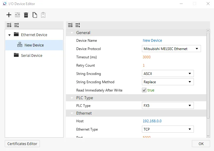
Mitsubishi MELSEC Ethernet
Canvas supports Mitsubishi MELSEC Ethernet as a way to connect with other devices that support this protocol. Users can select a Mitsubishi PLC Type within the settings to suit specific configurations better. Users will also be able to choose a Frame Type for the MELSEC.
Supported Symbols
| Name | Symbol | Bit Range | Word Range | Address Number System | Access |
|---|---|---|---|---|---|
| Input | X | X0000 - X1757 (1777) | - | Octal | R |
| Output | Y | Y0000 - Y1757 | - | Octal | R |
| Internal Relay | M | M0000 - M7659 | - | Decimal | R/W |
| Latching Relay | L | L0000 - L7659 | - | Decimal | R/W |
| Annunciator | F | F000 - F107 | - | Decimal | R/W |
| Edge Relay | V | V0000 -V2029 | - | Decimal | R/W |
| Link Relay | B | B000 - B0EF | - | Hexadecimal | R/W Not supported for iQ-F FX5 |
| Step Relay | S | S0000 - S4079 | - | Decimal | R/W |
| Timer Contact | TS | TS000 - TS496 | - | Decimal | R/W |
| Timer Coil | TC | TC000 - T496 | - | Decimal | R/W |
| Retentive Timer Contact | SS | SS00 - SS00 | - | Decimal | R/W |
| Retentive Timer Coil | SC | SC00 - SC00 | - | Decimal | R/W |
| Counter Contact | CS | CS000 - CS240 | - | Decimal | R/W |
| Counter Coil | CC | CC000 - CC240 | - | Decimal | R/W |
| Link Special Relay | SB | SB000 - SB1EF | - | Hexadecimal | R/W |
| Special Relay | SM | SM0000 - SM9979 | - | Decimal | R/W |
| Data Register | D | - | D0000 - D7999 | Decimal | R/W |
| Link Register | W | - | W000 - W1FF | Hexadecimal | R/W |
| Timer CV | TN | - | TN000 - TN511 | Decimal | R/W |
| Retentive Timer CV | SN | - | SN00 - SN15 | Decimal | R/W |
| Counter CV | CN | - | CN000 - CN255 | Decimal | R/W |
| Link Special Register | SW | - | SW000 - SW1FF | Hexadecimal | R/W |
| Special Register | SD | - | SD00000 - SD11999 | Decimal | R/W |
Communication Cable Wiring
This interface is satisfied with standard IEEE802.3 about the 10BaseT/100BaseTX. You can configure the cable and allocation pin number of RJ45 as shown below.
| RJ45 Connector | RJ45 Jack |
|---|---|
| |
Direct Cable: Host <-> HUB
| Cable | No. | Color | Color | No. | Cable |
|---|---|---|---|---|---|
| 1 | Orange/White | Orange/White | 1 | |
| 2 | Orange | Orange | 2 | ||
| 3 | Green/White | Green/White | 3 | ||
| 4 | Blue | Blue | 4 | ||
| 5 | Blue/White | Blue/White | 5 | ||
| 6 | Green | Green | 6 | ||
| 7 | Brown/White | Brown/White | 7 | ||
| 8 | Brown | Brown | 8 |
Crossover Cable: Host <-> Host
| Cable | No. | Color | Color | No. | Cable |
|---|---|---|---|---|---|
| 1 | Orange/White | Green/White | 1 | |
| 2 | Orange | Green | 2 | ||
| 3 | Green/White | Orange/White | 3 | ||
| 4 | Blue | Blue | 4 | ||
| 5 | Blue/White | Blue/White | 5 | ||
| 6 | Green | Orange | 6 | ||
| 7 | Brown/White | Brown/White | 7 | ||
| 8 | Brown | Brown | 8 |
Modbus TCP
Canvas supports Modbus TCP as a way to connect with other devices that support this protocol. Users can Swap 16 for Integers, Strings, Float32 and Float64, Swap 32 for Integer, Float32, Float64, and Swap 64 for Integer and Float64. Users will also have to set the Unit Identifier for Modbus TCP to correctly identify the device it is trying to connect to.
Address and Function Codes
The memory areas listed below are provided for general purposes. The actual available memory area and range of each area should be checked with the manual for the connecting device. The ‘Read’/’Write’ columns show the MODBUS function codes used in this communication driver.
The symbol character has to be placed in the first position of the address string. The address number follows the symbol character.
The following table shows the list of valid address ranges and used MODBUS function codes for each address area:
| Area | Symbol | Analog Tag | Digital Tag | Read | Write |
|---|---|---|---|---|---|
| Coil | 0 | 000001 - 029991 | 1 | 5 | |
| Input | 1 | 100001 - 129999 | 2 | ||
| Holding Register | 4 | 400001 - 429999 | 3 | 6, 162 | |
| Input Register | 3 | 300001 - 329999 | 4 |
-
The symbol character does not behave as a number. For example, 400100 and 40100 designate the same memory area (holding register 100).
-
Code 16 is issued for writing double words or when the recipe write function is activated. When writing single words, code 6 is used.
Communication Cable Wiring
This interface is satisfied with standard IEEE802.3 about the 10BaseT/100BaseTX. You can configure the cable and allocation pin number of RJ45 as shown below.
| RJ45 Connector | RJ45 Jack |
|---|---|
| |
Direct Cable: Host <-> HUB
| Cable | No. | Color | Color | No. | Cable |
|---|---|---|---|---|---|
| 1 | Orange/White | Orange/White | 1 | |
| 2 | Orange | Orange | 2 | ||
| 3 | Green/White | Green/White | 3 | ||
| 4 | Blue | Blue | 4 | ||
| 5 | Blue/White | Blue/White | 5 | ||
| 6 | Green | Green | 6 | ||
| 7 | Brown/White | Brown/White | 7 | ||
| 8 | Brown | Brown | 8 |
Crossover Cable: Host <-> Host
| Cable | No. | Color | Color | No. | Cable |
|---|---|---|---|---|---|
| 1 | Orange/White | Green/White | 1 | |
| 2 | Orange | Green | 2 | ||
| 3 | Green/White | Orange/White | 3 | ||
| 4 | Blue | Blue | 4 | ||
| 5 | Blue/White | Blue/White | 5 | ||
| 6 | Green | Orange | 6 | ||
| 7 | Brown/White | Brown/White | 7 | ||
| 8 | Brown | Brown | 8 |
ODVA EtherNet/IP
Canvas supports ODVA EtherNet/IP as a way to connect with other devices that support this protocol. Users using this method can set the Message Type for how the message should function when connected to another device that supports ODVA EtherNet/IP.
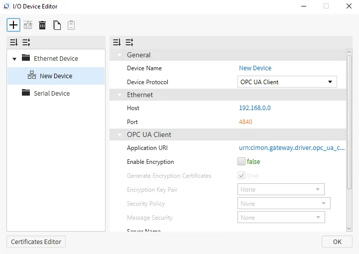
OPC UA Client
Canvas supports OPC UA Client as a way to connect to other devices that support this protocol. Users can Enable Encryption and enhance security for their OPC UA Client. Users can also manage specific Security Policies and change the authentication method.
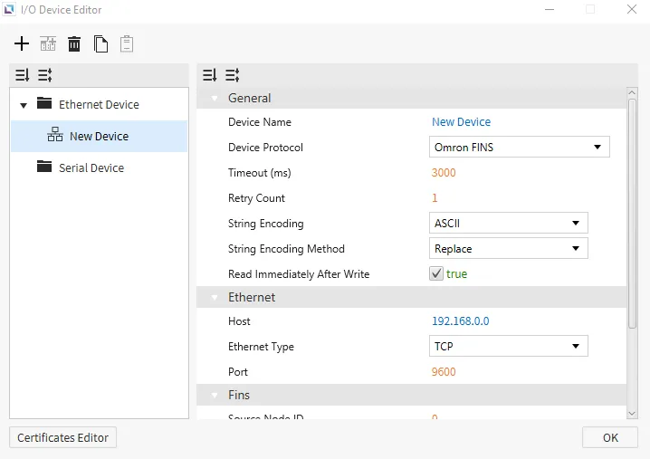
Omron FINS
Canvas supports Omron FINS as a way to connect to other devices that support this protocol. Users will need to set up Fins to use it. Users must specify the ID of the Source Node, Source Network, Destination Network, Destination Node, and Destination Unit to have Omron FINS set up correctly.
Supported Symbols
CS1/CJ1
| Name | Symbol | Bit Range | Word Range | Address Number System | Access |
|---|---|---|---|---|---|
| Auxiliary Relay | A | A000.00 - A447.15 | A000 - A447 | Decimal | R |
| A448.00 - A959.15 | A448 - A959 | Decimal | R/W | ||
| Common I/O | CIO | CIO0000.00 - CIO6143.15 | CIO0000 - CIO6143 | Decimal | R/W |
| Counter | CV | - | CV0000 - CV4095 | Decimal | R/W |
| Counter Status | CC | CC0000 - CC4095 | - | Decimal | R/W |
| Data Memory | D | D00000.00 - D32767.15 | D00000 - D32767 | Decimal | R/W |
| Expansion Data Memory | E | E0.00000.00 - EC_32767.15 | E0.00000 - EC_32767 | E{Bank number}_{start addr.} Bank number: Hexadecimal Start address: Decimal | R/W |
| Holding Relay | H | H0000.00 - H1535.15 | H0000 - H1535 | Decimal | R/W |
| Index Register | IR | - | IR00 - IR15 | Decimal | R/W |
| Timer | TV | - | TV0000 - TV4095 | Decimal | R/W |
| Timer Status | TC | TC0000 - TC4095 | - | Decimal | R/W |
| Working Relay | W | W000.00 - W511.15 | W000 - W511 | Decimal | R/W |
CJ2
| Name | Symbol | Bit Range | Word Range | Address Number System | Access |
|---|---|---|---|---|---|
| Auxiliary Relay | A | A000.00 - A447.15 | A000 - A447 | Decimal | R |
| A448.00 - A1471.15 | A448 - A1471 | Decimal | R/W | ||
| A10000.00 - A11535.15 | A10000 - A11535 | Decimal | R/W | ||
| Common I/O | CIO | CIO0000.00 - CIO6143.15 | CIO0000 - CIO6143 | Decimal | R/W |
| Counter | CV | - | CV0000 - CV4095 | Decimal | R/W |
| Counter Status | CC | CC0000 - CC4095 | - | Decimal | R/W |
| Data Memory | D | D00000.00 - D32767.15 | D00000 - D32767 | Decimal | R/W |
| Expansion Data Memory | E | E0.00000.00 - EC_32767.15 | E0.00000 - EC_32767 | E{Bank number}_{start addr.} Bank number: Hexadecimal Start address: Decimal | R/W |
| Holding Relay | H | H0000.00 - H1535.15 | H0000 - H1535 | Decimal | R/W |
| Index Register | IR | - | IR00 - IR15 | Decimal | R/W |
| Timer | TV | - | TV0000 - TV4095 | Decimal | R/W |
| Timer Status | TC | TC0000 - TC4095 | - | Decimal | R/W |
| Working Relay | W | W000.00 - W511.15 | W000 - W511 | Decimal | R/W |
Communication Cable Wiring
This interface is satisfied with standard IEEE802.3 about the 10BaseT/100BaseTX. You can configure the cable and allocation pin number of RJ45 as shown below.
| RJ45 Connector | RJ45 Jack |
|---|---|
| |
Direct Cable: Host <-> HUB
| Cable | No. | Color | Color | No. | Cable |
|---|---|---|---|---|---|
| 1 | Orange/White | Orange/White | 1 | |
| 2 | Orange | Orange | 2 | ||
| 3 | Green/White | Green/White | 3 | ||
| 4 | Blue | Blue | 4 | ||
| 5 | Blue/White | Blue/White | 5 | ||
| 6 | Green | Green | 6 | ||
| 7 | Brown/White | Brown/White | 7 | ||
| 8 | Brown | Brown | 8 |
Crossover Cable: Host <-> Host
| Cable | No. | Color | Color | No. | Cable |
|---|---|---|---|---|---|
| 1 | Orange/White | Green/White | 1 | |
| 2 | Orange | Green | 2 | ||
| 3 | Green/White | Orange/White | 3 | ||
| 4 | Blue | Blue | 4 | ||
| 5 | Blue/White | Blue/White | 5 | ||
| 6 | Green | Orange | 6 | ||
| 7 | Brown/White | Brown/White | 7 | ||
| 8 | Brown | Brown | 8 |
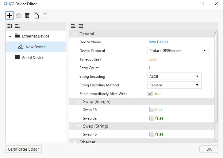
Proface GPEthernet
Canvas supports Proface GPEthernet as a way to connect to devices that support this protocol. Users will be able to Swap 16 for Integers and Strings and also Swap 32 for Integers.
Supported Symbols
| Name | Symbol | Bit Range | Word Range | Address Number System | Access |
|---|---|---|---|---|---|
| - | - | - | 0000 - 8191 | Decimal | R/W |
The following addresses cannot be accessed.
-
Address < 20
-
2032 < Address < 2096
-
8191 < Address
Communication Cable Wiring
This interface is satisfied with standard IEEE802.3 about the 10BaseT/100BaseTX. You can configure the cable and allocation pin number of RJ45 as shown below.
| RJ45 Connector | RJ45 Jack |
|---|---|
| |
Direct Cable: Host <-> HUB
| Cable | No. | Color | Color | No. | Cable |
|---|---|---|---|---|---|
| 1 | Orange/White | Orange/White | 1 | |
| 2 | Orange | Orange | 2 | ||
| 3 | Green/White | Green/White | 3 | ||
| 4 | Blue | Blue | 4 | ||
| 5 | Blue/White | Blue/White | 5 | ||
| 6 | Green | Green | 6 | ||
| 7 | Brown/White | Brown/White | 7 | ||
| 8 | Brown | Brown | 8 |
Crossover Cable: Host <-> Host
| Cable | No. | Color | Color | No. | Cable |
|---|---|---|---|---|---|
| 1 | Orange/White | Green/White | 1 | |
| 2 | Orange | Green | 2 | ||
| 3 | Green/White | Orange/White | 3 | ||
| 4 | Blue | Blue | 4 | ||
| 5 | Blue/White | Blue/White | 5 | ||
| 6 | Green | Orange | 6 | ||
| 7 | Brown/White | Brown/White | 7 | ||
| 8 | Brown | Brown | 8 |
Siemens S7
Canvas supports Siemens S7 as a way to connect to devices that support this protocol. Users can set up the Slot Number and Rack Number of the S7. This will need to be correct to grab information from the correct device.
Supported Symbols
| Name | Symbol | Bit Range | Word Range | Address Number System | Access |
|---|---|---|---|---|---|
| Process Inputs | I | I0.0 - I1023.7 (Max 65535.7) | I0 - I1023 (Max 65535) | Decimal | R/W |
| Process Outputs | Q | Q0.0 - Q1023.7 (Max 65535.7) | Q0 - Q1023 (Max 65535) | Decimal | R/W |
| Merkers | M | M0.0 - M4095.7 (Max 65535.7) | M0 - M4095 (Max 65535) | Decimal | R/W |
| DB | DB | DB0,0.0 - DB65535,65535.7 | DB0,0 - DB65535,65535 | Decimal | R/W |
| Counters | C | - | C0 - C65535 | Decimal | R/W |
| Timer | T | - | T0 - T65535 | Decimal | R/W |
S7 1200/1500 notes:
-
Only global DBs can be accessed.
-
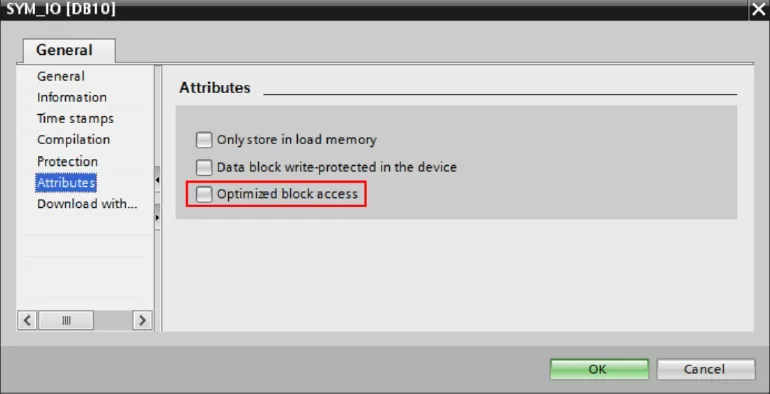
To access a DB memory area in S7 1200/1500, some additional settings in PLC software (TIA Portal) are required.
-
The optimized block access must be turned off.
- Select the DB in the left pane under “Program blocks” and press [Alt+Enter]. (Or in the contextual menu, select “Properties…”)
- Uncheck Optimized block access
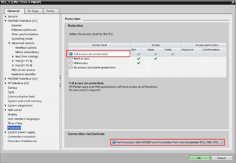
- The access level must be “full,” and the “connection mechanism” must allow GET/PUT.
- Select the CPU project in the left pane and press [Alt+Enter]. (Or in the contextual menu, select “Properties…”.)
- Select “Full access” and check “Permit access with PUT/GET …” as in the image below.
Communication Cable Wiring
This interface is satisfied with standard IEEE802.3 about the 10BaseT/100BaseTX. You can configure the cable and allocation pin number of RJ45 as shown below.
| RJ45 Connector | RJ45 Jack |
|---|---|
| |
Direct Cable: Host <-> HUB
| Cable | No. | Color | Color | No. | Cable |
|---|---|---|---|---|---|
| 1 | Orange/White | Orange/White | 1 | |
| 2 | Orange | Orange | 2 | ||
| 3 | Green/White | Green/White | 3 | ||
| 4 | Blue | Blue | 4 | ||
| 5 | Blue/White | Blue/White | 5 | ||
| 6 | Green | Green | 6 | ||
| 7 | Brown/White | Brown/White | 7 | ||
| 8 | Brown | Brown | 8 |
Crossover Cable: Host <-> Host
| Cable | No. | Color | Color | No. | Cable |
|---|---|---|---|---|---|
| 1 | Orange/White | Green/White | 1 | |
| 2 | Orange | Green | 2 | ||
| 3 | Green/White | Orange/White | 3 | ||
| 4 | Blue | Blue | 4 | ||
| 5 | Blue/White | Blue/White | 5 | ||
| 6 | Green | Orange | 6 | ||
| 7 | Brown/White | Brown/White | 7 | ||
| 8 | Brown | Brown | 8 |
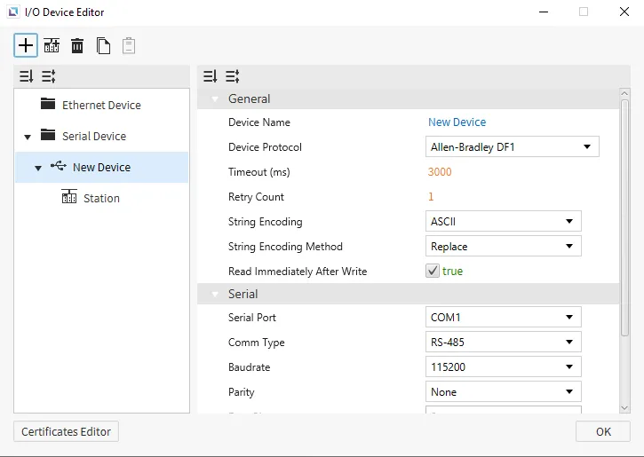
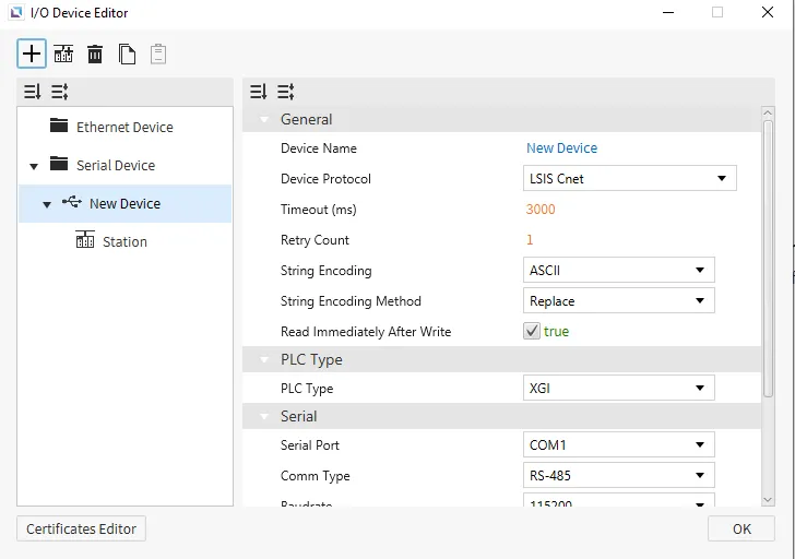
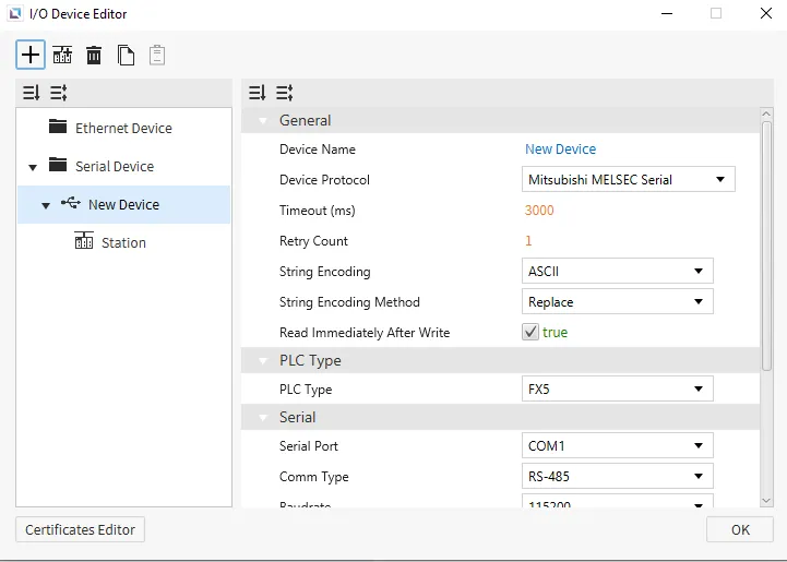
Serial Device
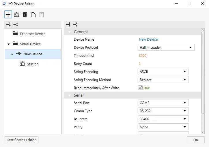
Serial Devices are used when a connection to another device is made via a serial cable. Users will need to input the Serial Port of the device they are connecting to, the Comm Type, and the Baudrate. Users can also select the String Encoding and the String Encoding Method. Users can also change settings such as the Timeout time, Retry Count, and Transmission Delay. Users will also be able to change the name of the Device and the Protocol of the device as well.

Allen-Bradley DF-1
Canvas supports Allen-Bradley DF-1 as a way to connect to devices that support this protocol. Users will be able to select the Error Detection and Flow Control for the protocol. Users can choose between BCC and CRC for Error Detection, and can turn on, off or control Flow Control. No additional settings will appear after selecting the device.
Supported Format
| Name | Symbol | Digital | Analog |
|---|---|---|---|
| BOOL (BOOL) | B | B0:0/0 - B999:999/31 | B3:0 - B3:255 |
| INT (WORD) | N | N0:0/0 - N999:999/15 | N7:0 - N7:255 |
| REAL (FLOAT) | F | F0:0/0 - F999:999/31 | F8:0 - F8:255 |
Address Format
| Name | Symbol | Bit Range | Word Range |
|---|---|---|---|
| Output | O | O:0.0/0 – O:30.255/15 | O:0.0 – O:30.255 |
| Input | I | I:0.0/0 – I:30.255/15 | I:0.0 – I:30.255 |
| Status | S | S:0/0 – S:163/15 | S:0 – S:163 |
| Binary | B | B3:0/0 – B3:255/15 B9:0/0 – B255:255/15 | B3:0/0 – B3:255/15 B9:0/0 – B255:255/15 |
| Integer | N | N7:0/0 – N7:255/15 N9:0/0 – N255:255/15 | N7:0 – N7:255 N9:0 – N255:255 |
| Float | F | - | F8:0 – F255:255 New Registration is allowed in Float only. |
| Long | L | - | L9:0 – L255:255 New Registration is allowed in UINT32, INT32 only. |
| String | ST | - | ST9:0 – ST255:255 |
| Timer | T | T4:0.0/0 – T4:255.2/15 Txx:nn .0/15 Txx:nn .0/14 Txx:nn .0/13 | T4:0.0 – T4:255.2 T9:0.0 - T255:255.2 Txx:nn .1 = Preset Value (PRE) Txx:nn .2 = Accumulated Value (ACC) |
| Counter | C | C5:0.0/0 – C5:255.2/15 Cxx:nn .0/15 Cxx:nn .0/14 Cxx:nn .0/13 Cxx:nn .0/12 Cxx:nn .0/11 Cxx:nn .0/10 | C5:0.0 – C5:255.2 C9:0.0 – C255:255.2 Cxx:nn .1 = Preset (PRE) Cxx:nn .2 Accumulated Value (ACC) |
| Control | R | R6:0.0/0 – R6:255.2/15 Rxx:nn .0/15 Rxx:nn .0/14 Rxx:nn .0/13 Rxx:nn .0/12 Rxx:nn .0/11 Rxx:nn .0/10 Rxx:nn .0/9 Rxx:nn .0/8 | R6:0.0 – R6:255.2 R9:0.0 – R255:255.2 Rxx:nn .1 = Length value Rxx:nn .2 = position value |
Communication Wiring
The 1761-CBL-PM02 cable was used to develop this protocol, and will work when attempting to connect using this protocol.
CIMON PLC
This is the default protocol for Canvas. Users will be able to choose any of the CIMON PLCs under PLC Type. No additional settings will appear after any of the CIMON PLCs are selected.
Communication Settings: PLC
| Setting | Details |
|---|---|
| Communication Module | If using one of the following PLC modules to communicate with Xpanel, the card settings must be configured in CICON as shown below: CM1 - CN01M CM1 - CN01S CM3 - SP02ERS CM3 - SP02ERR CM3 - SP02ERC CM3-SP02ERSC BPnnMxxx - U 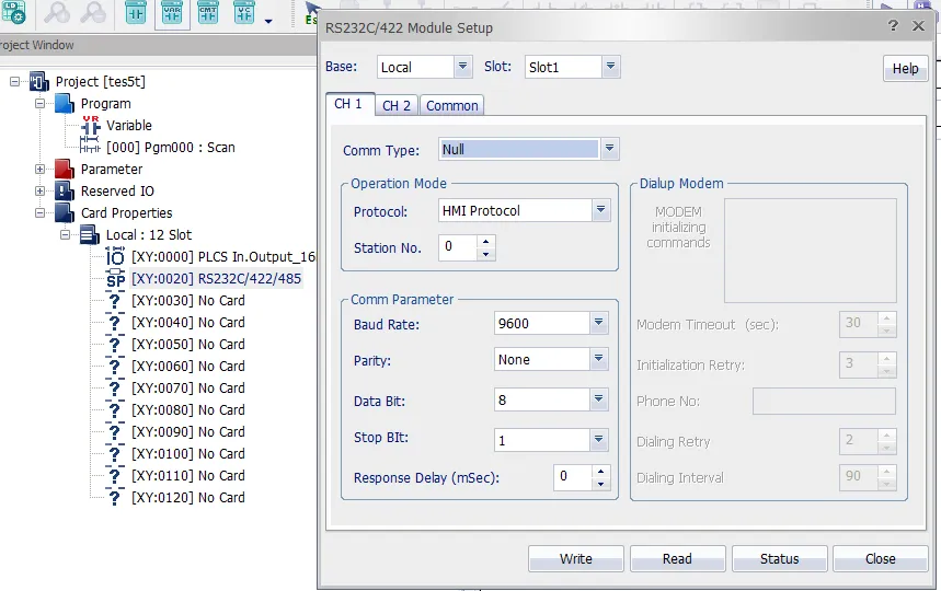 Note that the [CH 1] tab is for usage with RS232 connections, while the [CH 2] tab is for usage with RS485 connections. All communication parameters must match the settings chosen during the I/O device configuration in Canvas. Once the correct parameters have been entered, press the [Write] button while online with the PLC to update the communication parameters. |
| CPU Built-in Communication Port | If using a built-in CPU (PLC) serial port to communicate with Xpanel, the channel settings must be configured in CICON as shown below: This connection option is available with the following models: CM1 - XP Series CM1 - CP Series BPnnMxxx - S PLC-S 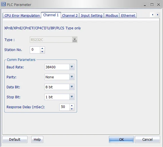 All communication parameters must match the settings chosen during the I/O device configuration in Canvas. All communication parameters must match the settings chosen during the I/O device configuration in Canvas. |
Hallim Loader
Canvas supports Hallim Loader as a way to connect to devices that support this protocol. No additional settings will appear on the selection of this protocol.
Memory Area and Ranges
| Area | Symbol | Analog Tag | Digital Tag | Access |
|---|---|---|---|---|
| External Input | X | X0000 - X5110 | X0000 - X511F | R/W |
| External Output | Y | Y0000 - Y5110 | Y0000 - Y511F | R/W |
| Internal Relay | M | M0000 - M9990 | M0000 - M999F | R/W |
| Internal Relay | L | L0000 - L9990 | L0000 - L999F | R/W |
| Latch Relay | K | K0000 - K9990 | K0000 - K999F | R/W |
| Flags | F | F0000 - F1270 | F0000 - F127F | R |
| Timer Output | T | - | T0000 - T4095 | R/W |
| Timer PV | TC | TC0000 - TC4095 | - | R/W |
| Timer SV | TS | TS0000 - TS4095 | - | R/W |
| Counter Output | C | - | C0000 - C4095 | R/W |
| Counter PV | CC | CC0000 - CC4095 | - | R/W |
| Counter SV | CS | CS0000 - CS4095 | - | R/W |
| Data Memory | D | D00000 - D31999 | - | R/W |
Communication Cable Wiring
| Model | Image |
|---|---|
| eXT07/nXT07 COM1: RS-422/485 COM2: RS-232C | 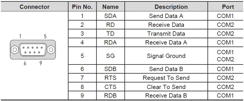 |
| eXT10/12/15 COM1: RS-422/485 COM2: RS-232C COM3: RS-232C | COM1 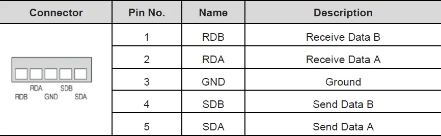 COM2 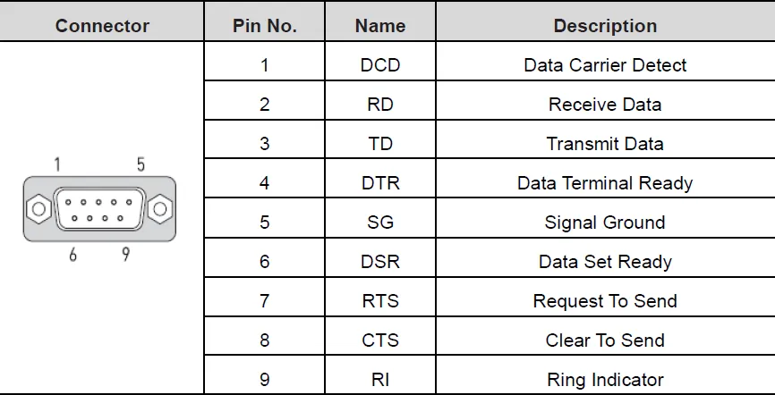 COM3 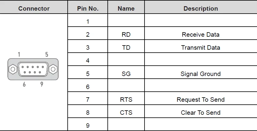 |
The above picture shows the RS-232C and RS-422/485 ports of the Xpanel. Please refer to your device manual for signal descriptions.
For the RS-232C ports, Xpanel provides the standard DB9 RS-232C pin assignment.
LSIS Cnet
Canvas supports LSIS Cnet as a way to connect to devices that support this protocol. Users will be able to choose any of the LSIS Cnet PLCs under PLC Type. No additional settings will appear under either of the PLC Type options.
XGK (XGK-CPU* / XBM / XBC)
| Name | Symbol | Bit Range | Word Range | Access |
|---|---|---|---|---|
| Input/Output | P | P00000 - P2047F | P0000 - P2047 | R/W |
| Binary | M | M00000 - M2047F | M0000 - M2047 | R/W |
| Binary | L | L000000 - L11263F | L00000 - L11263 | R/W |
| Non-Volatile Binary | K | K00000 - K4095F | K0000 - K4095 | R/W If the CPU is XGK, the bit range is "K00000 - K2047F" and the word range is "K0000 - K2047". |
| Status | F | F00000 - F2047F | F0000 - F2047 | R |
| Timer | T | T0000 - T2047 | - | R/W |
| Counter | C | C0000 - C2047 | - | R/W |
| Control | S | - | - | - |
| Integer | D | - | D00000 - D32767 | R/W |
| Index | R | - | R00000 - R32767 | R/W XBM does not support the R and ZR. XBC supports only R. (R and ZR are the same device in the XBC.) |
| Index | ZR | - | ZR00000 - ZR65535 | R/W XBM does not support the R and ZR. XBC supports only R. (R and ZR are the same device in the XBC.) |
| Timer - Current Count | T | - | T0000 - T2047 | R/W |
| Counter - Current Count | C | - | C0000 - C2047 | R/W |
| Comm. Data Register | N | - | N00000 - N21503 | R/W |
| Integer | Z | - | Z000 - Z127 | R/W |
XGK (XGK-CPUSN / XGK-CPUHN / XGK-CPUUN)
| Name | Symbol | Bit Range | Word Range | Access |
|---|---|---|---|---|
| Input/Output | P | P00000 - P4095F | P0000 - P4095 | R/W |
| Binary | M | M00000 - M4095F | M0000 - M4095 | R/W |
| Binary | L | L000000 - L11263F | L00000 - L11263 | R/W |
| Non-Volatile Binary | K | K00000 - K4095F | K0000 - K4095 | R/W |
| Status | F | F00000 - F4095F | F0000 - F4095 | R |
| Timer | T | T0000 - T8191 | - | R/W |
| Counter | C | C0000 - C4095 | - | R/W |
| Control | S | - | S000 - S255 | R/W |
| Integer | D | - | D000000 - D524287 | R/W If the CPU is XGK-CPUSN, the word range is "D000000 - D262143". |
| Index | R | - | R00000 - R32767 | R/W |
| Index | ZR | - | ZR000000 - ZR524287 | R/W |
| Timer - Current Count | T | - | T0000 - T8191 | R/W |
| Counter - Current Count | C | - | C0000 - C4095 | R/W |
| Comm. Data Register | N | - | N00000 - N21503 | R/W |
| Integer | Z | - | Z000 - Z255 | R/W |
| Special Module Register | U | - | U00.00 - U7F.31 | R/W If the CPU is XGK-CPUSN, the word range is "U00.00 - U3F.31". |
XGI
XGI
| Name | Symbol | Ranges | Access |
|---|---|---|---|
| Input Points | I | Bit: %IX000.00.00 - %IX127.15.63 Byte: %IB000.00.0 - %IB127.15.7 Word: %IW000.00.0 - %IW127.15.3 DWord: %ID000.00.0 - %ID127.15.1 QWord: %IL000.00.0 - %IL127.15.0 | R/W |
| Output Points | Q | Bit: %QX000.00.00 - %QX127.15.63 Byte: %QB000.00.00 - %QB127.15.7 Word: %QW000.00.00 - %QW127.15.3 DWord: %QD000.00.0 - %QD127.15.1 QWord: %QL000.00.0 - %QL127.15.0 | R/W |
| Automatic Variable | A | Bit: %AX0000000 - %AX8388607 Byte: %AB0000000 - %AB1048575 Word: %AW000000 - %AW524287 DWord: %AD000000 - %AD262143 QWord: %AL000000 - %AL131071 | R/W |
| Direct Variable | M | Bit: %MX0000000 - %MX4194303 Byte: %MB0000000 - %MB524287 Word: %MW000000 - %MW262143 DWord: %MD000000 - %MD131071 QWord: %ML00000 - %ML65535 | R/W |
| Direct Variable | R | Bit: %RX0000000 - %RX524287 Byte: %RB00000 - %RB65535 Word: %RW00000 - %RW32767 DWord: %RD00000 - %RD16383 QWord: %RL0000 - %RL8191 | R/W |
| Direct Variable | W | Bit: %WX0000000 - %WX8388607 Byte: %WB0000000 - %WB1048575 Word: %WW000000 - %WW524287 DWord: %WD000000 - %WD262143 QWord: %WL000000 - %WL131071 | R/W |
| System Flag | F | Bit: %FX00000 - %FX65535 Byte: %FB0000 - %FB8191 Word: %FW0000 - %FW4095 DWord: %FD0000 - %FD2047 QWord: %FL0000 - %FL1023 | R |
| PID Flag | K | Bit: %KX000000 - %KX134399 Byte: %KB00000 - %KB16799 Word: %KW0000 - %KW8399 DWord: %KD0000 - %KD4299 QWord: %KL0000 - %KL2199 | R/W |
| HS Link Flag | L | Bit: %LX000000 - %LX180223 Byte: %LB00000 - %LB22527 Word: %LW00000 - %LW11263 DWord: %LD0000 - %LD5631 QWord: %LL0000 - %LL2815 | R/W |
| Analog Refresh Flag | U | Bit: %UX0.00.000 - %UX7.15.511 Byte: %UB0.00.000 - %UB7.15.63 Word: %UW0.00.000 - %UW7.15.31 DWord: %UD0.00.000 - %UD7.15.15 QWord: %UL0.00.000 - %UL7.15.7 | R/W |
| P2P Parameters Flag | N | Bit: %NX000000 - %NX401407 Byte: %NB00000 - %NB50175 Word: %NW00000 - %NW25087 DWord: %ND00000 - %ND12543 QWord: %NL0000 - %NL6271 | R/W |
Communication Cable Wiring
| Model | Image |
|---|---|
| eXT07/nXT07 COM1: RS-422/485 COM2: RS-232C | |
| eXT10/12/15 COM1: RS-422/485 COM2: RS-232C COM3: RS-232C | COM1 COM2 COM3 |
The above picture shows the RS-232C and RS-422/485 ports of the Xpanel. Please refer to your device manual for signal descriptions.
For the RS-232C ports, Xpanel provides the standard DB9 RS-232C pin assignment.
Mitsubishi MELSEC Serial
Canvas supports Mitsubishi MELSEC Serial as a way to connect to devices that support this protocol. Users will be able to choose any of the Mitsubishi PLCs under PLC Type. Users will also need to select the Frame Type for the PLC as well.
Address and Supported Symbols
The memory areas listed below are provided for general purposes. The actual available memory area and range of each area should be checked with the manual for the connecting device.
The symbol character has to be placed in the first position of the address string. The address number follows the symbol character.
| Name | Symbol | Bit Range | Word Range | Address Number System | Access |
|---|---|---|---|---|---|
| Input | X | X0000 - X1757 (1777) | - | Octal | R |
| Output | Y | Y0000 - Y1757 | - | Octal | R |
| Internal Relay | M | M0000 - M7659 | - | Decimal | R/W |
| Latching Relay | L | L0000 - L7659 | - | Decimal | R/W |
| Annunciator | F | F000 - F107 | - | Decimal | R/W |
| Edge Relay | V | V0000 -V2029 | - | Decimal | R/W |
| Link Relay | B | B000 - B0EF | - | Hexadecimal | R/W Not supported for iQ-F FX5 |
| Step Relay | S | S0000 - S4079 | - | Decimal | R/W |
| Timer Contact | TS | TS000 - TS496 | - | Decimal | R/W |
| Timer Coil | TC | TC000 - T496 | - | Decimal | R/W |
| Retentive Timer Contact | SS | SS00 - SS00 | - | Decimal | R/W |
| Retentive Timer Coil | SC | SC00 - SC00 | - | Decimal | R/W |
| Counter Contact | CS | CS000 - CS240 | - | Decimal | R/W |
| Counter Coil | CC | CC000 - CC240 | - | Decimal | R/W |
| Link Special Relay | SB | SB000 - SB1EF | - | Hexadecimal | R/W |
| Special Relay | SM | SM0000 - SM9979 | - | Decimal | R/W |
| Data Register | D | - | D0000 - D7999 | Decimal | R/W |
| Link Register | W | - | W000 - W1FF | Hexadecimal | R/W |
| Timer CV | TN | - | TN000 - TN511 | Decimal | R/W |
| Retentive Timer CV | SN | - | SN00 - SN15 | Decimal | R/W |
| Counter CV | CN | - | CN000 - CN255 | Decimal | R/W |
| Link Special Register | SW | - | SW000 - SW1FF | Hexadecimal | R/W |
| Special Register | SD | - | SD00000 - SD11999 | Decimal | R/W |
Communication Cable Wiring
| Model | Image |
|---|---|
| eXT07/nXT07 COM1: RS-422/485 COM2: RS-232C | |
| eXT10/12/15 COM1: RS-422/485 COM2: RS-232C COM3: RS-232C | COM1 COM2 COM3 |
The above picture shows the RS-232C and RS-422/485 ports of the Xpanel. Please refer to your device manual for signal descriptions.
For the RS-232C ports, Xpanel provides the standard DB9 RS-232C pin assignment.
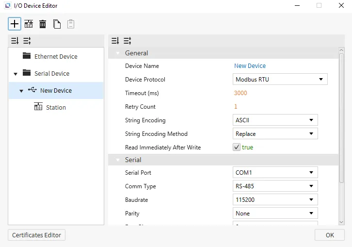
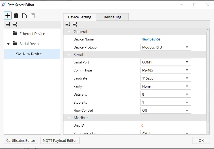
Modbus RTU
Canvas supports Modbus RTU as a way to connect to devices that support this protocol. Users will be able to change the Read Block Tolerance.
| Area | Symbol | Analog Tag | Digital Tag | Read | Write |
|---|---|---|---|---|---|
| Coil | 0 | 000001 - 029991 | 1 | 5 | |
| Input | 1 | 100001 - 129999 | 2 | ||
| Holding Register | 4 | 400001 - 429999 | 3 | 6, 162 | |
| Input Register | 3 | 300001 - 329999 | 4 |
-
The symbol character does not behave as a number. For example, 400100 and 40100 designate the same memory area (holding register 100).
-
Code 16 is issued for writing double words or when the recipe write function is activated. When writing single words, code 6 is used.
Communication Cable Wiring
| Model | Image |
|---|---|
| XPANEL COM/COM2 RS-232C | 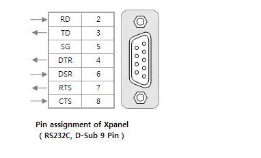 |
| XPANEL COM1 RS-422/485 | 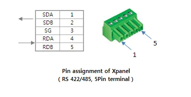 |
The above picture shows the RS-232C and RS-422/485 ports of the Xpanel. Please refer to your device manual for signal descriptions.
For the RS-232C ports, Xpanel provides the standard DB9 RS-232C pin assignment. Typically, RD, TD, and SG pins are enough to communicate with a general MODBUS device.
Omron HostLink
Canvas supports Omron Hostlink as a way to connect to devices that support this protocol. No additional settings will appear on the selection of this protocol.

Supported PLC Memories
| Area | Symbol | Analog Tag | Digital Tag | Remark |
|---|---|---|---|---|
| DM area | D | D0000 – D9999 | D0000.00 – D0000.15 | D9999.00 – D9999.15 |
| CIO area | CIO | CIO0000 – CIO6143 | CIO0000.00 – CIO0000.15 | CIO6143.00 – CIO6143.15 |
| AR area | A | A0000 – A0959 | A0000.00 – A0000.15 | A0959.00 – A0959.15 |
| HR area | H | H0000 – H0511 | H0000.00 – H0000.15 | H0511.00 – H0511.15 |
| T/C status | TC | not supported | TC0000 – TC4095 | (3) |
| T/C p. value | PV | PV0000 – PV4095 | not supported | (3) |
| LR area | L | L0000 – L0199 | L0000.00 – L0000.15 | L0199.00 – L0199.15 |
| EM area | E | E0_0000 – E0_9999 | EC_0000 – EC_9999 | E0_0000.00 – E0_0000.15 |
| IR area | IR | IR0000 – IR6143 | IR0000.00 – IR0000.15 | IR6143.00 – IR6143.15 |
-
If the address of this area was used for a digital tag, control functionalities are not supported. Xpanel cannot set/reset these points.
-
The A000 - A0447 address area cannot be modified by Xpanel (read-only area).
-
Timer: T0000 – T2143 area was mapped to TC0000 - TC2143 (PV0000 - PV2143).
-
Counter: C0000 – C2143 area was mapped to TC2148 - TC4095 (PV2148 - PV4095).
- The Bank of EM area must be denoted by one hexadecimal character ('0' - 'C') as shown below:
-
Digital Tag: E[bank]_[word no].[2 digit bit no] (EA_1000.05 : bit5 of E1000 in bank ‘A’).
-
Analog Tag: E[bank]_[word no] (EC_32 : E0032 of bank ‘C’).
- The bit location of the digital tag must be denoted by a two-digit decimal number ('00' - ‘15') with a dot ('.') separator.
*Exception: Timer/Counter area is a digital point by itself.
Wiring Diagram
| Model | Image |
|---|---|
| RS-232C | 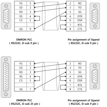 |
| C Series RS-422A | 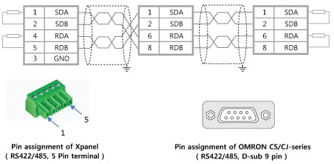 |
| CS/CJ Series RS-422A | |
Panasonic FP7
Canvas supports Panasonic FP7 as a way to connect to devices that support this protocol. No additional settings will appear on the selection of this protocol.
Address and Supported Symbols
The memory areas listed below are provided for general purposes. The actual available memory area and range of each area should be checked with the manual for the connecting device.
The symbol character has to be placed in the first position of the address string. The address number follows the symbol character.
| Name | Symbol | Bit Range | Word Range | Address Number System | Access |
|---|---|---|---|---|---|
| External input relay | X | X000.0 - X511.F | X000 - X511 | Decimal, Hexadecimal | R/W |
| External output relay | Y | Y000.0 - Y511.F | Y000 - Y511 | Decimal, Hexadecimal | R/W |
| Internal relay | R | R0000.0 - R2047.F | R0000 - R2047 | Decimal, Hexadecimal | R/W |
| Link relay | L | L0000.0 - L1023.F | L0000 - L1023 | Decimal, Hexadecimal | R/W |
| Data register | DT | DT000000.0 - DT999423.F | DT000000 - DT999423 | Decimal, Hexadecimal | R/W |
| Link register | LD | LD00000.0 - LD16383.F | LD00000 - LD16383 | Decimal, Hexadecimal | R/W |
| Timer set value register | TS | - | TS0000 - TS4095 | Decimal | R/W |
| Timer elapsed value register | TE | - | TE0000 - TE4095 | Decimal | R/W |
| Counter set value register | CS | - | CS0000 - CS1023 | Decimal | R/W |
| Counter elapsed value register | CE | - | CE0000 - CE1023 | Decimal | R/W |
| Timer (Contact) | T | T0000 - T4095 | - | Decimal | R |
| Counter (Contact) | C | C0000 - C1023 | - | Decimal | R |
| Pulse relay | P | P000 - P255 | - | Decimal | R |
| Error alarm relay | E | E0000 - E4095 | - | Decimal | R |
| Index register | I | - | I00 - I14 | Decimal | R/W |
| Unit memory | UM | UM000000.0 - UM524287.F | UM000000 - UM524287 | Decimal, Hexadecimal | R/W |
| Direct input | IN | - | IN00 - IN62 | Decimal | R |
| Direct output | OT | OT00.0 - OT62.F | OT00 - OT62 | Decimal, Hexadecimal | R/W |
| System relay | SR | - | SR0000 - SR0223 | Decimal | R |
| System data | SD | - | SD000 - SD255 | Decimal | R |
Communication Cable Wiring
| Model | Image |
|---|---|
| eXT07/nXT07 COM1: RS-422/485 COM2: RS-232C | |
| eXT10/12/15 COM1: RS-422/485 COM2: RS-232C COM3: RS-232C | COM1 COM2 COM3 |
The above picture shows the RS-232C and RS-422/485 ports of the Xpanel. Please refer to your device manual for signal descriptions.
For the RS-232C ports, Xpanel provides the standard DB9 RS-232C pin assignment.
Yokogawa FA-M3
Canvas supports Yokogawa FA-M3 as a way to connect to devices that support this protocol. No additional settings will appear on the selection of this protocol.
Address and Supported Symbols
Some memory areas have different addressing formats.
-
X, Y memory area addressing format
-
Format: {symbol}{1 digit for rack number}{2 digits for slot number}{2 digits for bit number}
-
Rack number: 0 - 7
-
Slot number: 00 - 12
-
Bit number: 00 - 63
-
L memory area addressing format
-
Format: {symbol}{1 digit for rack number}{4 digits for memory address}
-
Rack number: 0 - 7
-
Memory address: 0 - 1023
The memory areas listed below are provided for general purposes. The actual available memory area and range of each area should be checked with the manual for the connecting device.
The symbol character has to be placed in the first position of the address string. The address number follows the symbol character.
| Name | Symbol | Bit Range | Word Range | Address Number System | Access |
|---|---|---|---|---|---|
| Input relay | X | X00201 - X71649 | X00201 - X71664 | Decimal | R |
| Output relay | Y | Y00201 - Y71649 | Y00201 - Y71664 | Decimal | R/W |
| Internal relay | I | I0001 - I4081 | I0001 - I4096 | Decimal | R/W |
| Shared relay | E | E0001 - E2033 | E0001 - E2048 | Decimal | R/W |
| Link relay | L | L00001 - L71008 | L00001 - L71023 | Decimal | R/W |
| Special relay | M | M001 - M497 | M001 - M512 | Decimal | R/W |
| Data register | D | - | D0001 - D5120 | Decimal | R/W |
| Shared register | R | - | R0001 - R1024 | Decimal | R/W |
| Index register | V | - | V01 - V16 | Decimal | R/W |
| File register | B | - | - | - | - |
| Link register | W | - | W0001 - W1024 | Decimal | R/W |
| Special register | Z | - | Z001 - Z256 | Decimal | R/W |
| Timer relay | TU | TU001 - TU256 | - | Decimal | R/W |
| Timer current value | TP | - | TP001 - TP256 | Decimal | R |
| Timer current value | TI | - | TI001 - TI256 | Decimal | R |
| Timer present value | TS | - | TS001 - TS256 | Decimal | R/W |
| Counter relay | CU | CU001 - CU256 | - | Decimal | R/W |
| Counter current value | CP | - | CP001 - CP256 | Decimal | R |
| Counter current value | CI | - | CI001 - CI256 | Decimal | R |
| Counter present value | CS | - | CS001 - CS256 | Decimal | R/W |
Communication Cable Wiring
| Model | Image |
|---|---|
| eXT07/nXT07 COM1: RS-422/485 COM2: RS-232C | |
| eXT10/12/15 COM1: RS-422/485 COM2: RS-232C COM3: RS-232C | COM1 COM2 COM3 |
The above picture shows the RS-232C and RS-422/485 ports of the Xpanel. Please refer to your device manual for signal descriptions.
For the RS-232C ports, Xpanel provides the standard DB9 RS-232C pin assignment.
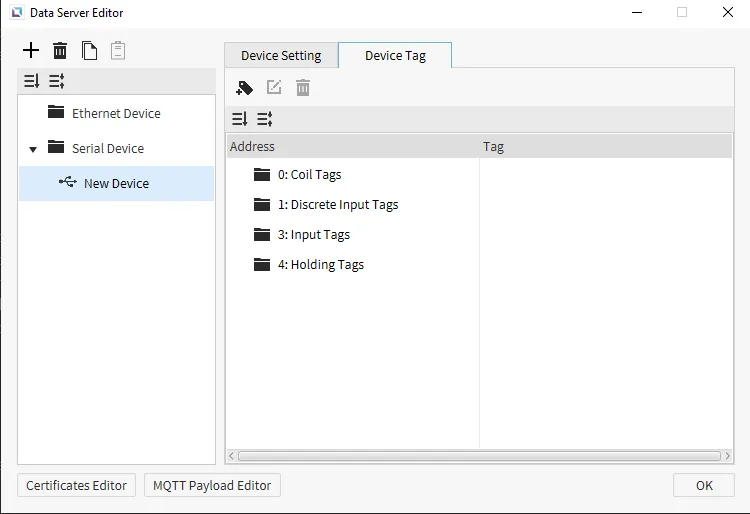
Data Server Editor
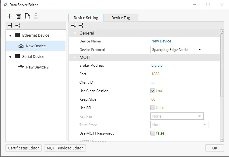
To access the Data Server Editor, go to Tools > Data Server Editor or click the Open Data Server Editor… on the toolbar to open it. To create a new device, click the + icon to open the Add New Server Device screen. Users can select the Connection Type of ethernet or serial for that specific device. Users can also select the Device Type, which will open a dropdown of specific devices that Canvas supports connecting to. Once selected, the Data Server will be created with default settings.
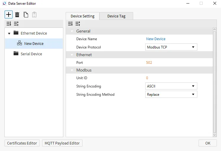
Ethernet Device
Ethernet devices are used when the connection to another device is via an Ethernet connection. Users will need to input the Port of the device they are connecting to for it to connect successfully. For Modbus TCP, users will need to enter the Unit ID via Modbus to connect successfully and the String Encoding and String Encoding Method.
Note: Aside from Modbus TCP Port 502, only numbers above 1023 are supported as Port numbers.
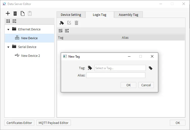
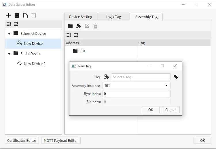
EtherNet/IP Server
The EtherNet/IP Server can be used to connect to a hosted EtherNet/IP Client device. All tags can be included or mentioned explicitly as Logix tags for data transfer. An Assembly Instance may be added with an Assembly Instance Number and Data Size. Then, an Assembly tag may be assigned to the Assembly Instance using a Byte Index and Bit Index.
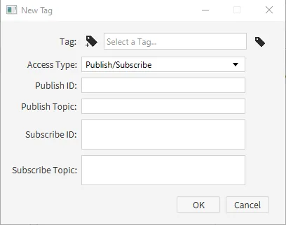
MQTT JSON Publisher
The MQTT JSON Publisher can be used to publish to the user and subscribe to read tag data. Users can set Subscribe Topic and Publish Topic to follow the subscribe/publishing method for MQTT JSON Publisher.
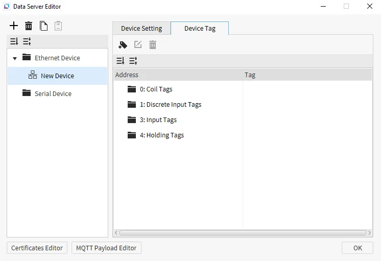
Modbus TCP/RTU
Modbus TCP and RTU host memories with the following memory areas: 0, 1, 3, and 4. Users must use the MODBUS address of the address they wish to target. If, for example, the user wishes to target Y00, the tag must target 000001. Depending on the tag data type, a different range of addresses will also be allocated.
In CIMON PLCs, 0 refers to Y, 1 refers to X, 4 refers to D, and 3 refers to M.
OPC UA Server
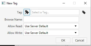
OPC UA Server tags must have a unique Browse Name. Users must set whether the Tag can be Allowed Read and Allowed Write when creating the Device Tag for the OPC UA Server.
The address used by the client will be ns=2;s=<server prefix>.<browse name>. Depending on the settings of the OPC UA Server, if the Server Layout is set to Basic, then the format will be ns=2;s=Tags.browseName, or if it is set to Device, then it will be ns=2;s=Tags.deviceName.browseName.

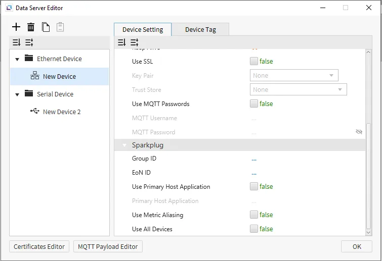
Sparkplug Edge Node
The Sparkplug Edge Node is an MQTT based protocol that facilitates messages between clients using a publisher/subscriber topic system. Connected clients can subscribe to specific topics and the broker will only send it messages on those subscribed topics. The Group ID and EoN ID act as identifiers include in the topic structure.
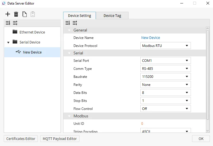
Serial Device
Serial Devices are used when a connection to another device is made via a serial cable. Users will need to input the Serial Port of the device they are connecting to, the Comm Type, and the Baudrate. Users can also select the PLC Type, the String Encoding, and the String Encoding Method. Users will also be able to change the name of the Device and the Protocol of the device as well. For Modbus TCP, users must enter the Unit ID via Modbus to connect successfully and the String Encoding and String Encoding Method. Modbus RTU is currently the only protocol for Serial Devices on Data Server Editor.
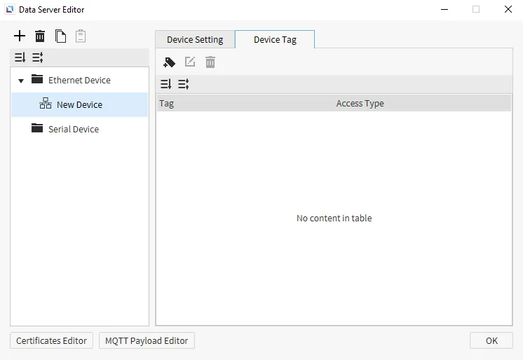
Device Tag
Device tags are used to connect tags with the server. The created server will host any tags listed within the Device Tag tab. Within the tab, addresses and other properties for each tag can be configured. Each protocol will have different settings for the Device Tag screen.
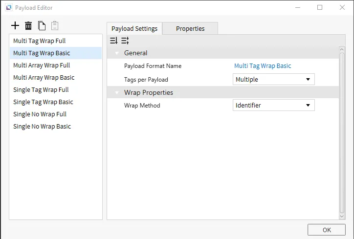
MQTT Payload Editor
MQTT Payload Editor lets users edit the MQTT message sent to the server. This will allow users to configure how payloads are configured for specific devices to match the required format. Users can configure Multi Tag Wrap Basic and Multi Tag Wrap Full as an example and change how many Tags per Payload and the Wrap Method. These can be configured within the MQTT Payload Editor as needed.
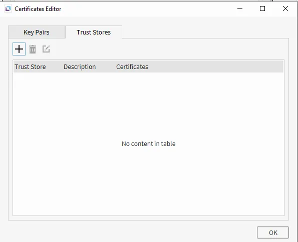
Certificate Editor
The Certificate Editor is used to create and edit certificate files, which can be used to encrypt and authorize any connection to the project. Users can use this feature to add more security and encryption to their projects so that no unauthorized access can happen. Users can use their own Private Key and Certificate for their project.
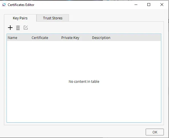
Key Pairs
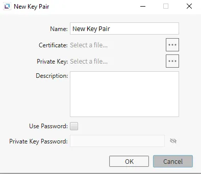
The Key Pairs page is where users can see their current Key Pairs. Clicking the + icon will create a new Key Pair. Users will need to insert a Name, a Certificate, a Private Key, and a Description. Users can also add a Password for the Private Key as an additional layer of security. Users will also be able to Delete and Edit any current Key Pairs they have.
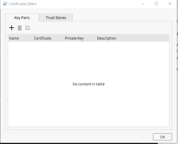
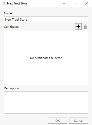
Trust Stores
There is also a Trust Stores tab, where users can put all known certificates they use within the project. This is where certificates will be verified by the project to confirm that they are acceptable. Users can click the + icon to create a new Trust Store. This will open the New Trust Store pop-up page. Users will need to add a Name, Certifications, and a Description. Users can Delete and Edit any Trust Stores already created.