Data Bridge Exercise
Understanding Data Bridge
Data Bridge in Canvas allows two or more PLCs to communicate through an HMI without them being directly connected to each other. This is useful when different PLC brands are used in a system, as they may not natively support direct communication. By using the HMI as a bridge, data can be exchanged between these devices, allowing seamless integration. In this exercise, a CIMON PLC and a Siemens S7 PLC will be connected using an Xpanel as the bridge, with Canvas managing the data transfer.
The process involves using two pre-configured PLCs in Canvas, creating the necessary data tags, setting up the Data Bridge function, and then visualizing the data transfer using on-screen objects in an HMI interface. This will all be tested using the Online Simulator.
Setting Up the I/O Devices
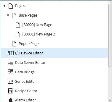
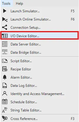
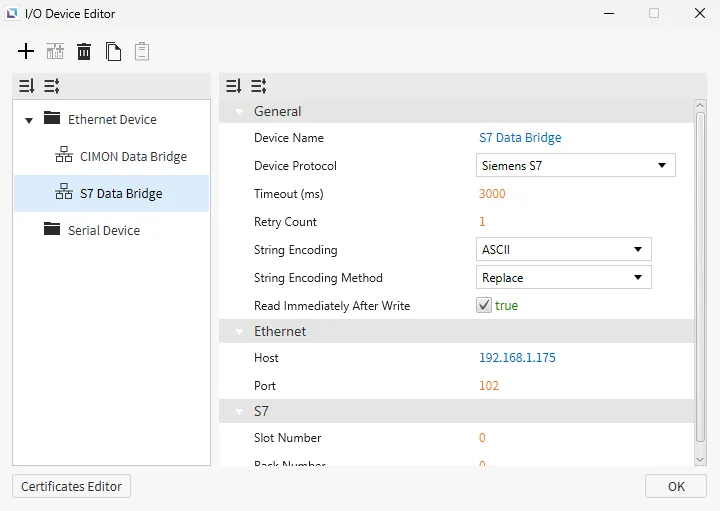
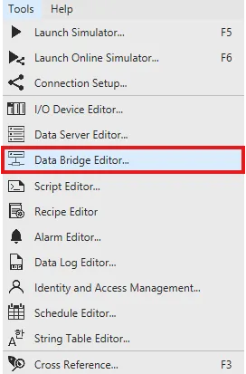
To enable communication between the HMI and the PLCs, the devices must be registered in Canvas. Open the I/O Device Editor by selecting it from the Project Tree on the left side of the screen or by navigating to Tools > I/O Device Editor.
In the I/O Device Editor, select Ethernet Device, add a new device named CIMON Data Bridge using the CIMON PLC (HMI Protocol). Set the IP to 192.168.1.163.
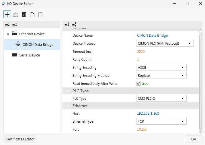
Add another device named S7 Data Bridge. Set the device type to Siemens S7 and the IP address to 192.168.1.175.
Creating Data Tags
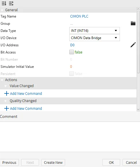
Data tags act as variables that store values being transferred between devices. These tags will be assigned to each PLC so that data can be read from one and written to another.
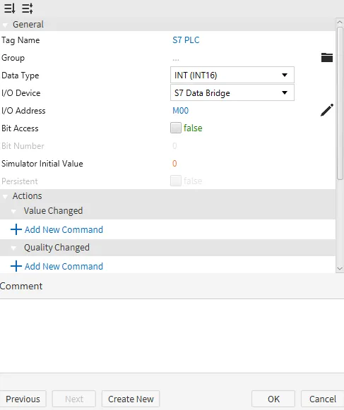
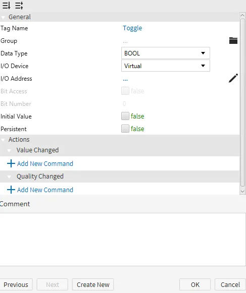
Create three tags: the first one will be named CIMON PLC with the type set to INT (INT16), I/O Device set to CIMON Data Bridge, and the I/O Address D0. The second tag will be named S7 PLC with the type set to INT (INT16), I/O Device set to S7 Data Bridge, and the I/O Address M00. The last tag will be named Toggle with the type set to BOOL. This will remain a virtual tag.
Configuring the Data Bridge
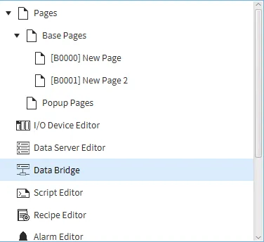
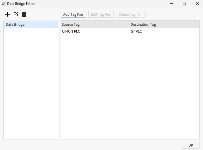
Open the Data Bridge Editor from the Project Tree or the Tools menu.
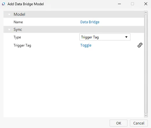
Create a new Data Bridge model. Give it a name and set the sync type to Trigger Tag. Bind the trigger tag to the Toggle tag created earlier.
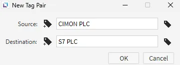
Add a new tag pair with the CIMON PLC tag as the Source, and the S7 PLC tag as the Destination.
Designing the HMI Interface
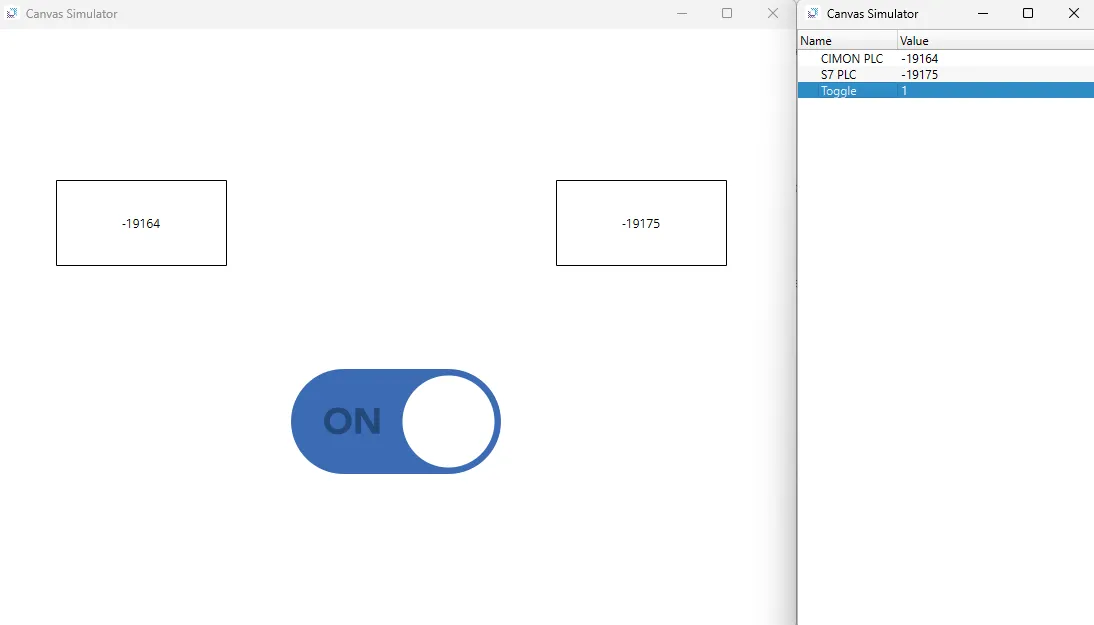
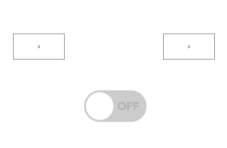
Add two numeric field objects to the screen. On the left object, smart-bind the CIMON PLC tag. On the right object, smart-bind the S7 PLC tag. Below the two numeric field objects, insert a toggle button. Smart-bind the Toggle tag to the toggle button.
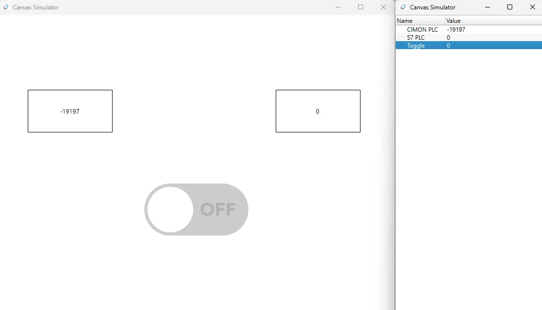
Running the Online Simulator
Open the Online Simulator. The CIMON PLC tag will update its value every second. The S7 PLC will NOT receive any updates until the toggle button is set to on.
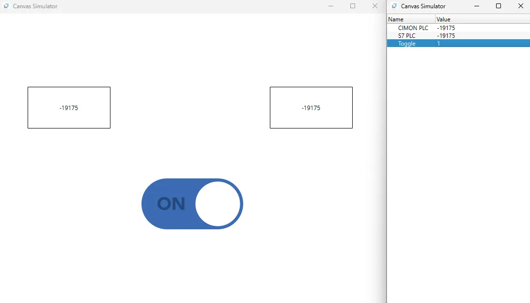
The CIMON PLC will continue updating every second. However, the S7 PLC will not update until the toggle button is toggled off and on again.