Skip to content Exercise: Demonstrating the use of the Tag Editor
Tag Editor Configuration
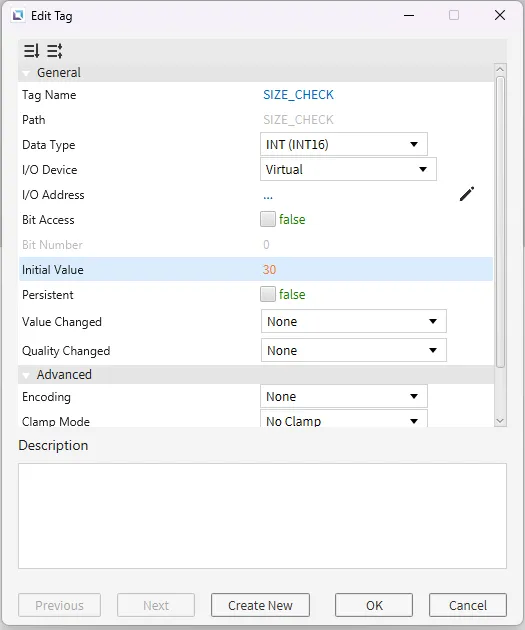
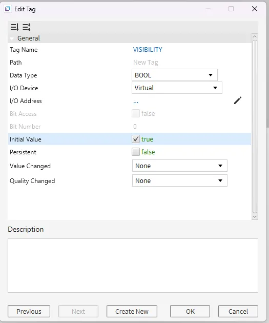
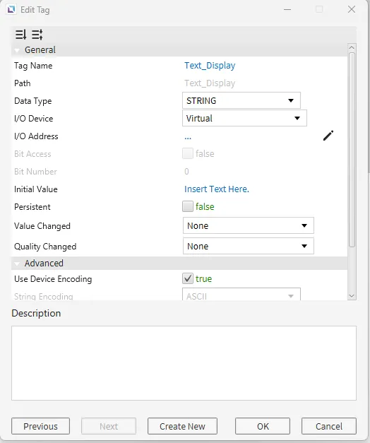
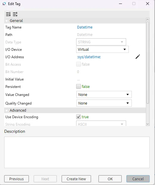
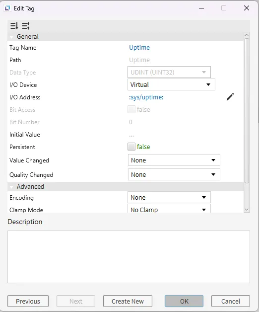
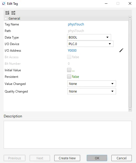
- Create six tags. To create a new Tag, go to Tag Editor and click on the Add Tag button to begin creating the tag. Create the following tags: Size_check as an INT (INT16), with an Initial Value of 30. Visibility as a BOOL. Set the Initial Value to True. Text_Display as a String. The Initial Value will be “Insert Text Here.” Another Tag called “Date/Time”. Click the Pencil next to the I/O Address on the Edit Tag Page and select System in the Type dropdown. Then, under Value, select Datetime String. Click OK to save the changes and click OK again to exit. Now create a tag named “Uptime”. Click the Pencil next to the I/O Address on the Edit Tag Page and select System in the Type dropdown. Then, under Value, select System Uptime (MS). Click OK to save the changes and click OK again to exit. Lastly, create a tag called “physTouch.” This tag will be a bool, and the I/O Device will be “PLC.” The I/O Address will be Y0000. (Note: The user has already defined an I/O device named “PLC” in this example. If your I/O Device has a different name, then enter that name into the I/O Device field. Likewise, if the I/O address format differs, use the correct form for your PLC).
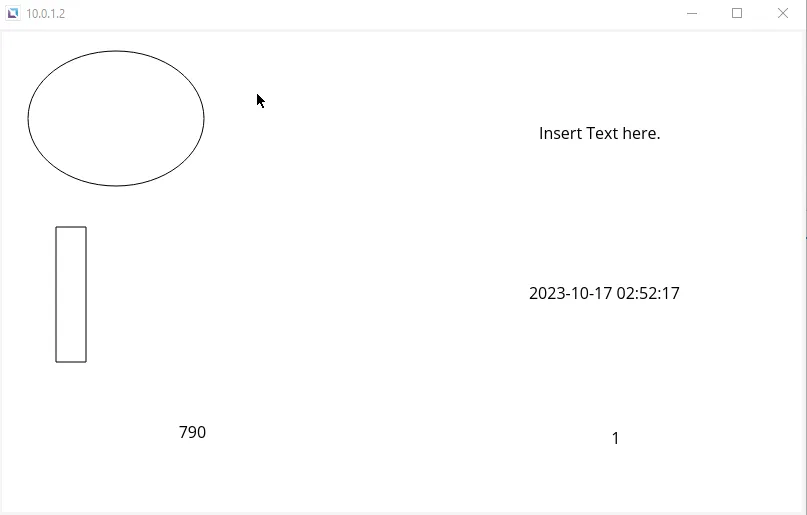
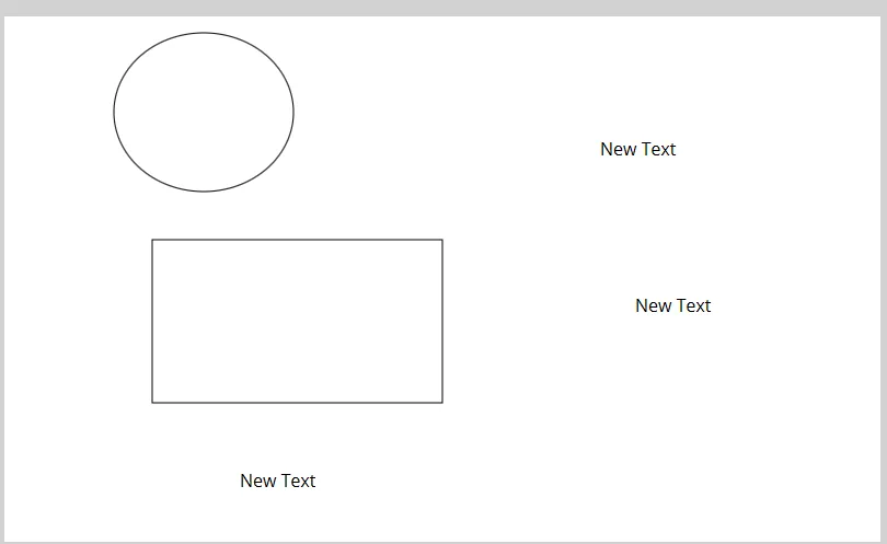
- Now, create objects that will properly utilize these tags created—first, a Rectangle. Click on the Insert Rectangle or go to Insert > Rectangle to begin drawing it. Then, create four Text Fields, click Insert Text, or go to Insert > Text. Last, create an Ellipse. Click Insert Ellipse in the toolbar, or go to Insert > Ellipse.
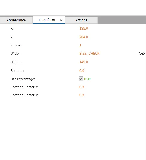
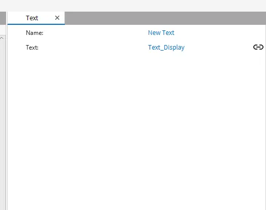
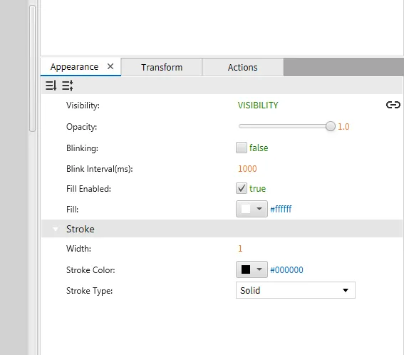
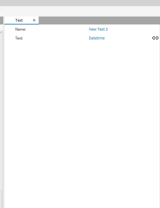
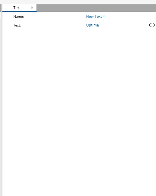
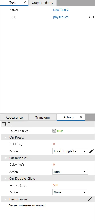
- Connect the Tags to the objects, first for Text_Display. Click and drag Text_Display onto the Text Box created. This will automatically bind the tag to the Text within the Text box and display the current String. For Visibility, click on the ellipse under Appearance and hover over Visibility until an Icon appears on the right side. Click this Icon, and under Tag, select the Visibility Tag. Once selected, click OK. For Size_Check, bind this to the Width of the rectangle. To do this, select the Rectangle, go under Transform, then click and drag Size_check to Width. This will smart bind the tag to the Width of the Rectangle. For the last three Text boxes, drag either Datetime, Uptime, or physTouch into one of the text boxes. Then click and drag the last one into the remaining text box. For the text box with physTouch, go to the Actions tab. Then, under On Press, select the Create New Commands option. Make a Toggle Tag Value command, and bind the physTouch tag to the command. Click OK to save the changes and exit out.
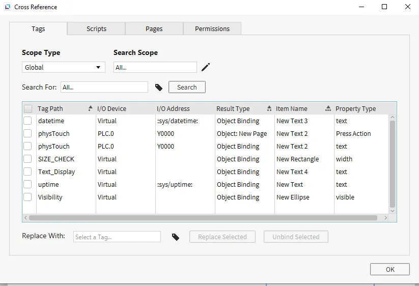
- Use the Cross Reference tool to confirm that tags are correctly bound without checking each object. To use it, press F3 or go to Tools > Cross Reference. This will display the current tags bound to the project and the property they are attached to. Use this to confirm if the tags are bound to the correct part of the object.
Tag Editor Runtime
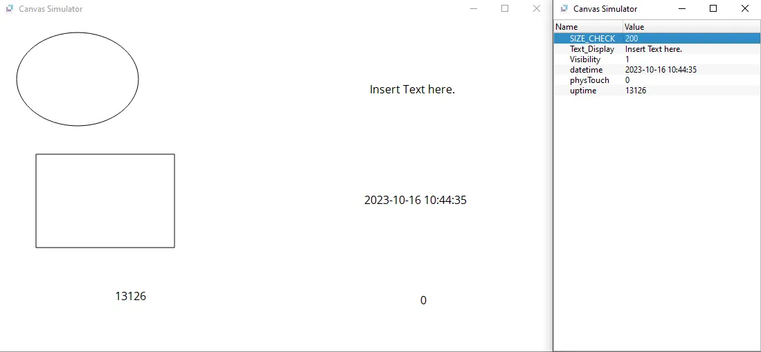
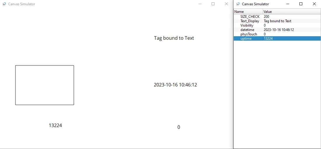
- Click Tools > Launch Simulator to launch the Canvas Simulator.
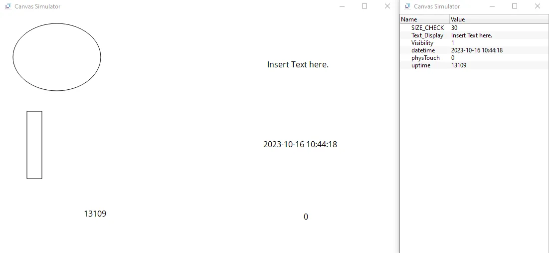
- Change Size_check from 30 to 200. The width of the rectangle should now change. This will indicate that the tag was correctly bound.
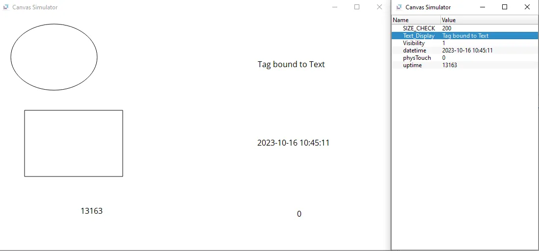
- Change Text_Display to “Tag bound to Text.” The Text in the box should also change to indicate that the tag was bound correctly.
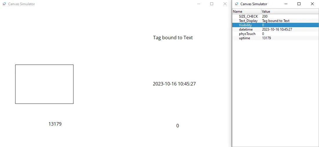
- Now, change the Visibility to 0 (false). This should hide the ellipse and will indicate that the tag is bound to the visibility property.
- Now try to change the DateTime tag to any number. Due to it being read directly from the system, no manual value changes can be made.
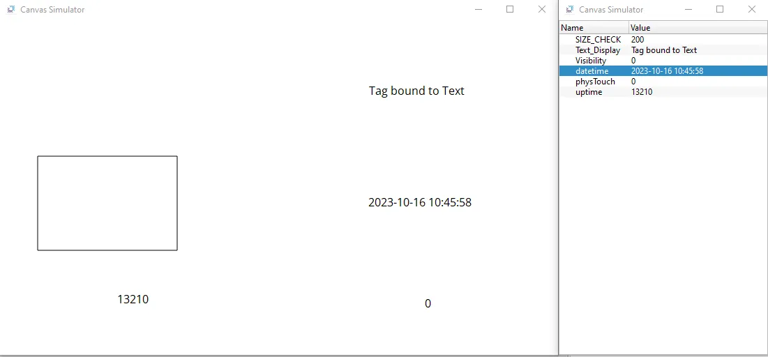
- Attempt the above step with the Uptime, and, similar to DateTime, due to it being read directly from the system, no manual value changes can be made.
- Under Tools > Connection Setup find the HMI you wish to upload the project on, then upload it by clicking Download (PC → HMI). Wait for it to finish uploading to the HMI. Once it is finished downloading, it should open on the HMI. Touch the text that is connected to the physical device. The number should change from 0 to 1. This indicates that the device is communicating with the PLC properly.