Ethernet Device Communication
Ethernet Devices
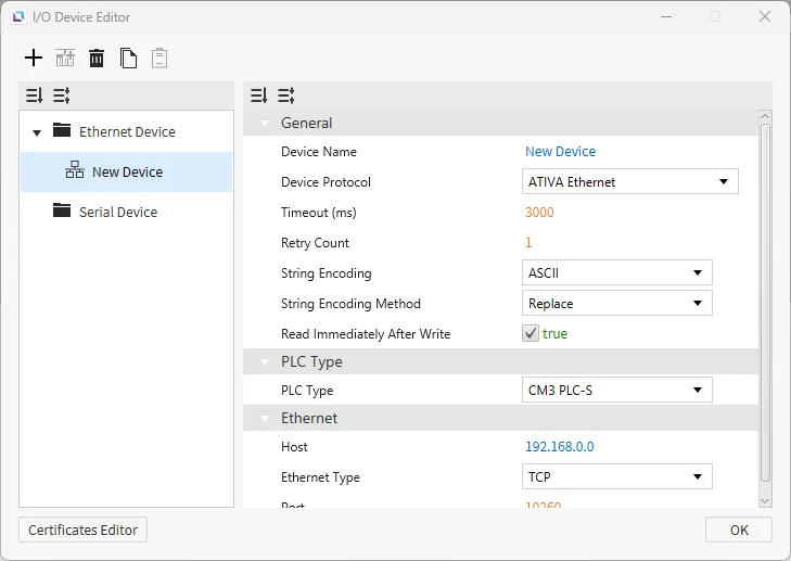
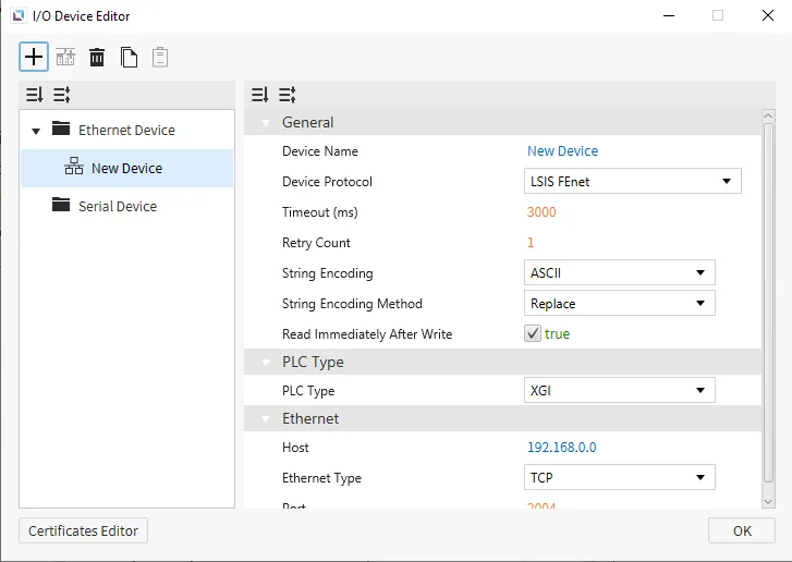
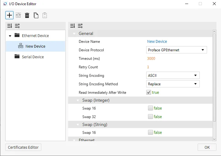
Ethernet devices are used when the connection to another device is via an Ethernet connection. Users must input the IP of the device they are connecting to, the Ethernet Type, and the Port. Depending on the selected protocol, users can also set the PLC Type. Users can also select the String Encoding and the String Encoding Method. Other settings, such as the Timeout time and the Retry Count, can be configured. Users will also be able to change the name of the device and the communication protocol.

Communication Cable Wiring
Ethernet-supported I/O devices will use the following cables:
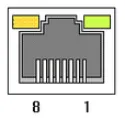
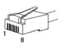
RJ45
This interface is satisfied with standard IEEE802.3 about the 10BaseT/100BaseTX. You can configure the cable and allocation pin number of RJ45 as shown below.
| RJ45 Connector | RJ45 Jack |
|---|---|
 |  |
Straight-Through Cable (Host ↔ Hub)
The straight-through cable is used when connecting the Xpanel to the I/O device through an Ethernet hub or switch acting as an intermediary.
| Cable | No. | Color | Color | No. | Cable |
|---|---|---|---|---|---|
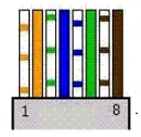 | 1 | Orange/White | Orange/White | 1 | 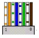 |
| 2 | Orange | Orange | 2 | ||
| 3 | Green/White | Green/White | 3 | ||
| 4 | Blue | Blue | 4 | ||
| 5 | Blue/White | Blue/White | 5 | ||
| 6 | Green | Green | 6 | ||
| 7 | Brown/White | Brown/White | 7 | ||
| 8 | Brown | Brown | 8 |
Crossover Cable (Host ↔ Host)
The crossover cable is used when connecting the Xpanel directly to the I/O device.
| Cable | No. | Color | Color | No. | Cable |
|---|---|---|---|---|---|
| 1 | Orange/White | Green/White | 1 | 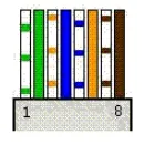 |
| 2 | Orange | Green | 2 | ||
| 3 | Green/White | Orange/White | 3 | ||
| 4 | Blue | Blue | 4 | ||
| 5 | Blue/White | Blue/White | 5 | ||
| 6 | Green | Orange | 6 | ||
| 7 | Brown/White | Brown/White | 7 | ||
| 8 | Brown | Brown | 8 |
Supported Drivers
ATIVA Ethernet
Canvas supports the ATIVA Ethernet protocol. This protocol is the basic HMI protocol to connect with other ATIVA devices. Users can select the ATIVA PLC Type that they are working with. There are no additional options for any of the ATIVA PLCs; the settings will remain the same across all ATIVA PLCs.
Format
- Analog Tag Format: {Symbol}{Address Number}
- Example: D0 retrieves the full WORD value.
- Digital Tag Format: {Symbol}{Address Number}{Bit Number}
- Example: D0A retrieves the 10th bit value of the WORD D0.
Memory Area and Ranges
| Memory Area | Symbol | Digital | Analog | Access |
|---|---|---|---|---|
| External Input | X | X000.0 - X511.F | X0000 - X5110 | R |
| External Output | Y | Y000.0 - Y511.F | Y0000 - Y5110 | R/W |
| Internal Relay | M | M000.0 - M999.F | M0000 - M9990 | R/W |
| Internal Relay | L | L000.0 - L999.F | L0000 - L9990 | R/W |
| Latch (Non-Volatile) Relay | K | K000.0 - K999.F | K0000 - K9990 | R/W |
| Flags | F | F000.0 - F127.F | F0000 - F1270 | R |
| Timer - Output | T | T0000 - T4095 | - | R/W |
| Timer - Current Value | TC | - | TC0000 - TC4095 | R/W |
| Timer - Set Value | TS | - | TS0000 - TS4095 | R/W |
| Counter - Output | C | C0000 - C4095 | - | R/W |
| Counter - Current Value | CC | - | CC0000 - CC4095 | R/W |
| Counter - Set Value | CS | - | CS0000 - CS4095 | R/W |
| Step Controller | S | - | S00 - S99 | R/W |
| Data Memory | D | D00000.0 - D31999.F | D00000 - D31999 | R/W |
| Index Register | R | - | R00 - R19 | R/W |
| Subroutine | Z | - | Z0000 - Z1029 | R/W |
| Sequential Function Chart | Q | Q000.0 - Q511.F | Q0000 - Q5110 | R/W |
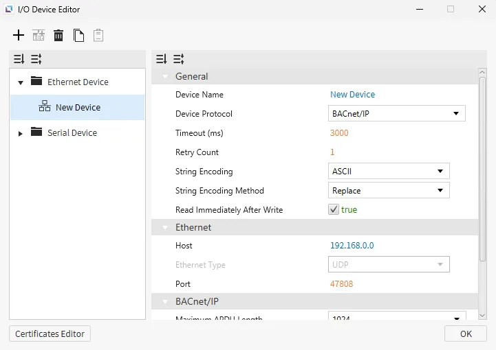
BACnet/IP
Canvas supports BACnet/IP Ethernet communication. Users can configure the Maximum APDU Length, Use Read Property Multiple, Maximum Items per Request, and Write Request Priority.
Format
- Format Option 1:
- {Object Type Name}.{Instance Number}.{Property Name}
- {Object Type Name}.{Instance Number}.{Property Name}[Array Index]
- Format Option 2:
- {Object Type ID}.{Instance Number}.{Property ID}
- {Object Type ID}.{Instance Number}.{Property ID}[Array Index]
Supported Standard Object Types and Properties
Supported Objects
Object ID range: 0 ~ 1,023
| Object Type Name | Object Type ID |
|---|---|
| AnalogInput | 0 |
| AnalogOutput | 1 |
| AnalogValue | 2 |
| BinaryInput | 3 |
| BinaryOutput | 4 |
| BinaryValue | 5 |
| Device | 8 |
| MultiStateInput | 13 |
| MultiStateOutput | 14 |
| MultiStateValue | 19 |
| LifeSafetyPoint | 21 |
| LifeSafetyZone | 22 |
Supported Instance Number
Instance number range: 0 ~ 4,194,302
Supported Properties
Property ID range: 0 ~ 4,194,303
| Property Name | Property ID | Note |
|---|---|---|
| Description | 28 | String type only |
| EventState | 36 | - |
| NumberOfStates | 74 | - |
| ObjectID | 75 | - |
| ObjectName | 77 | String type only |
| ObjectType | 79 | - |
| PresentValue | 85 | - |
| PriorityArray | 87 | Array type Use [] to access an element |
| Units | 117 | - |
| Mode | 160 | - |
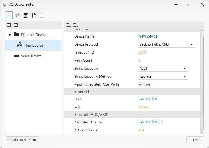
Beckhoff ADS/AMS
Canvas supports Beckhoff ADS/AMS as a way to connect with other devices that support this protocol. Users can configure the AMS Net ID Target and ADS Port Target.
Format
{Memory Area}{Data Type}{Memory Position}.{Bit Number}
Properties
- AMS Net ID Target
- This is the address of the target device on the ADS/AMS network.
- The value must be a six-part numeric identifier in the format
X.X.X.X.X.Xwhere each segment ranges from 0 ~ 255.
- ADS Port Target
- This is the port number identifying the target service.
Memory Area and Ranges
| Symbol | Digital | Analog | Address Notation | Access |
|---|---|---|---|---|
| M | M0.0 - M65535.7 | M0 - M65535 | Decimal | R/W |
| MX | MX0.0 - MX65535.7 | - | Decimal | R/W |
| MB | - | MB0 - MB65535 | Decimal | R/W |
| MW | - | MW0 - MW65535 | Decimal | R/W |
| MD | - | MD0 - MD65535 | Decimal | R/W |
| I | I0.0 - I65535.7 | I0 - I65535 | Decimal | R/W |
| IX | IX0.0 - IX65535.7 | - | Decimal | R/W |
| IB | - | IB0 - IB65535 | Decimal | R/W |
| IW | - | IW0 - IW65535 | Decimal | R/W |
| ID | - | ID0 - ID65535 | Decimal | R/W |
| Q | Q0.0 - Q65535.7 | Q0 - Q65535 | Decimal | R/W |
| QX | QX0.0 - QX65535.7 | - | Decimal | R/W |
| QB | - | QB0 - QB65535 | Decimal | R/W |
| QW | - | QW0 - QW65535 | Decimal | R/W |
| QD | - | QW0 - QW65535 | Decimal | R/W |
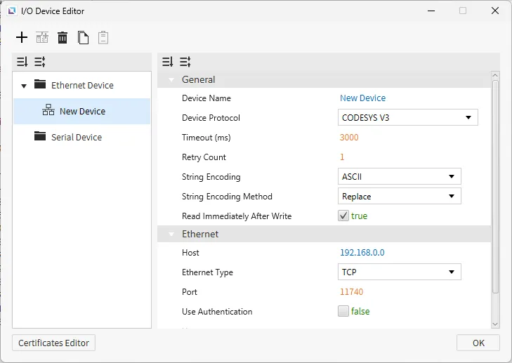
CODESYS V3
Canvas supports CODESYS V3 as a way to connect with other devices that support this protocol. This protocol allows for XML files to be imported as tags and establishes communication with PLC devices supporting CODESYS V3.
Authentication can be configured for logging into a CODESYS V3-supported device.
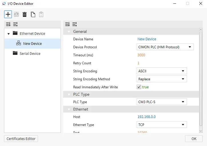
CIMON PLC (HMI Protocol)
CIMON PLC (HMI Protocol) is the default protocol for Canvas. This protocol is the basic HMI protocol to connect with other CIMON devices. Users can select the CIMON PLC Type that they are working with. There are no additional options for any of the CIMON PLCs; the settings will remain the same across all CIMON PLCs.
Format
- Analog Tag Format: {Symbol}{Address Number}
- Example: D0 retrieves the full WORD value.
- Digital Tag Format: {Symbol}{Address Number}{Bit Number}
- Example: D0A retrieves the 10th bit value of the WORD D0.
Memory Area and Ranges
| Memory Area | Symbol | Digital | Analog | Access |
|---|---|---|---|---|
| External Input | X | X000.0 - X511.F | X0000 - X5110 | R |
| External Output | Y | Y000.0 - Y511.F | Y0000 - Y5110 | R/W |
| Internal Relay | M | M000.0 - M999.F | M0000 - M9990 | R/W |
| Internal Relay | L | L000.0 - L999.F | L0000 - L9990 | R/W |
| Latch (Non-Volatile) Relay | K | K000.0 - K999.F | K0000 - K9990 | R/W |
| Flags | F | F000.0 - F127.F | F0000 - F1270 | R |
| Timer - Output | T | T0000 - T4095 | - | R/W |
| Timer - Current Value | TC | - | TC0000 - TC4095 | R/W |
| Timer - Set Value | TS | - | TS0000 - TS4095 | R/W |
| Counter - Output | C | C0000 - C4095 | - | R/W |
| Counter - Current Value | CC | - | CC0000 - CC4095 | R/W |
| Counter - Set Value | CS | - | CS0000 - CS4095 | R/W |
| Step Controller | S | - | S00 - S99 | R/W |
| Data Memory | D | D00000.0 - D31999.F | D00000 - D31999 | R/W |
| Index Register | R | - | R00 - R19 | R/W |
| Subroutine | Z | - | Z0000 - Z1029 | R/W |
| Sequential Function Chart | Q | Q000.0 - Q511.F | Q0000 - Q5110 | R/W |
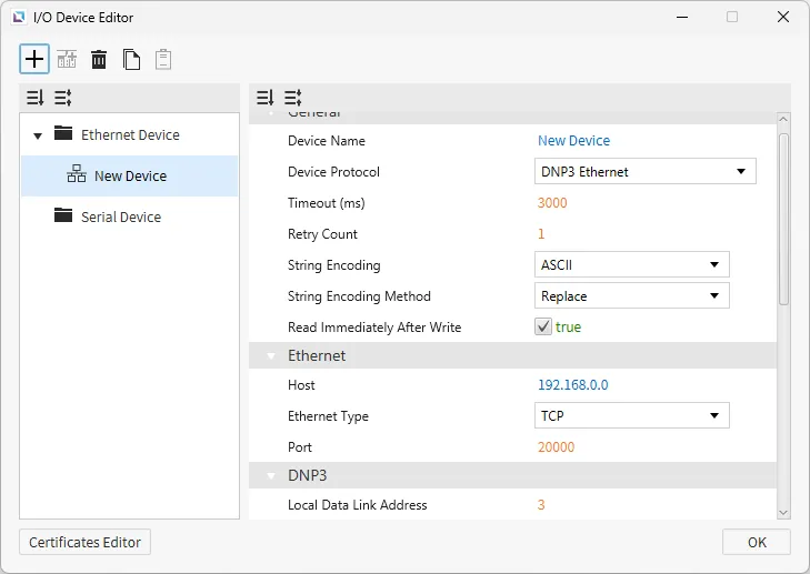
DNP3 Ethernet
Canvas supports DNP3 Ethernet as a way to connect with other devices that support this protocol. Users can configure Local Data Link Address, Remote Data Link Address, Explicit Scan Interval, Integrity Poll Interval, Class 1-3 Poll Interval, Unsolicited Event Class 1-3, Analog Operation Mode, Binary Operation Mode, Binary Operation Type, Time Sync Mode, Integrity On Start Up, and Integrity On Event Overflow.
Format
| Group | Variations | Digital | Analog | Address Notation | Access |
|---|---|---|---|---|---|
| 1: Binary Input | 0: Default Variation 1: Packet Format 2: With Flags | 1.{0, 1, 2}.{0-65535}.{Value, Explicit} | 1.{0, 1 ,2}.{0-65535}.{Flags, Timestamp} | Decimal | R |
| 3: Double Binary Input | 0: Default Variation 1: Packet Format 2: With Flags | - | 3.{0, 1, 2}.{0-65535}.{Value, Explicit, Flags, Timestamp} | Decimal | R |
| 10: Binary Output | 0: Default Variation 1: Packet Format 2: Output Status With Flags | 10.{0, 1, 2}.{0-65535}.{Value, Explicit} | 10.{0, 1, 2}.{0-65535}.{Flags, Timestamp} | Decimal | R/W(Value, Explicit) |
| 20: Counter | 0: Default Variation 1: 32-bit With Flag 2: 16-bit With Flag 5: 32-bit Without Flag 6: 16-bit Without Flag | - | 20.{0, 1, 2, 5, 6}.{0-65535}.{Value, Explicit, Flags, Timestamp} | Decimal | R |
| 21: Frozen Counter | 0: Default Variation 1: 32-bit With Flag 2: 16-bit With Flag 5: 32-bit With Flag and Time 6: 16-bit With Flag and Time 9: 32-bit Without Flag 10: 16-bit Without Flag | - | 21.{0, 1, 2, 5, 6, 9, 10}.{0-65535}.{Value, Explicit, Flags, Timestamp} | Decimal | R |
| 30: Analog Input | 0: Default Variation 1: 32-bit With Flag 2: 16-bit With Flag 3: 32-bit Without Flag 4: 16-bit Without Flag 5: Single-Precision With Flag 6: Double-Precision With Flag | - | 30.{0, 1, 2, 3, 4, 5, 6}.{0-65535}.{Value, Explicit, Flags, Timestamp} | Decimal | R |
| 40: Analog Output | 0: Default Variation 1: 32-bit With Flag 2: 16-bit With Flag 3: Single-Precision With Flag 4: Double-Precision With Flag | - | 40.{0, 1, 2, 3, 4}.{0-65535}.{Value, Explicit, Flags, Timestamp} | Decimal | R/W(Value, Explicit) |
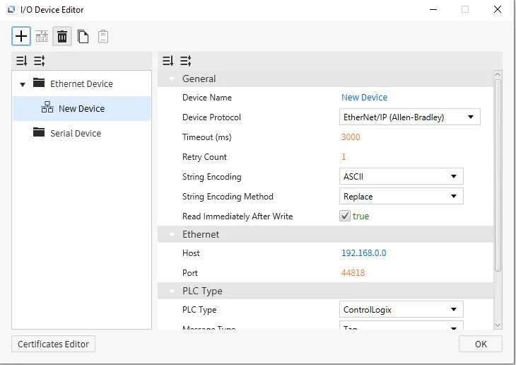
EtherNet/IP (Allen-Bradley)
Canvas supports Allen-Bradley's EtherNet/IP as a way to connect with other devices that support this protocol. Users will be able to select an Allen-Bradley PLC Type, the Message Type, and a toggle to Use Multiple Service.
ControlLogix & CompactLogix SLC Mapping (PCCC)
Format
- General Format: {Symbol}{File Number}:{Element Number}/{Bit Number}
Memory Area and Ranges
| Memory Area | Symbol | Digital | Analog | Address Notation | Access |
|---|---|---|---|---|---|
| Binary Files | B | B{0-999}:{0-65535}/{0-15} | B{0-999}:{0-65535} | Decimal | R/W |
| Integer Files | N | N{0-999}:{0-65535}/{0-15} | N{0-999}:{0-65535} | Decimal | R/W |
| Float Files | F | - | F{0-999}:{0-65535} | Decimal | R/W |
MicroLogix (PCCC)
Format
- General Format: {Symbol}{File Number}:{Element Number}/{Bit Number}
Memory Area and Ranges
| Memory Area | Symbol | Digital | Analog | Address Notation | Access |
|---|---|---|---|---|---|
| Output Files | O | O:0.0/0 - O:0.30/15 | O:0.0 - O:0.30 | Decimal | R/W |
| Input Files | I | I:0.0/0 - I:0.30/15 | I:0.0 - I:0.30 | Decimal | R |
| Status Files | S | S:0/0 - S:163/15 | S:0 - S:163 | Decimal | R |
| Binary Files | B | B3:0/0 - B3:255/15 B9:0/0 - B255:255/15 | B3:0 - B3:255 B9:0 - B255:255 | Decimal | R/W |
| Integer Files | N | N7:0/0 - N7:255/15 N9:0/0 - N255:255/15 | N7:0 - N7:255 N9:0 - N255:255 | Decimal | R/W |
| Float Files | F | - | F8:0 - F255:255 | Decimal | R/W |
| Long Files | L | - | L9:0 - F255:255 | Decimal | R/W |
| String Files | ST | - | ST9:0 - ST255:255 | Decimal | R/W |
| Timer Files | T | T4:0.0/0 - T4:255.2/15 T9:0.0/0 - T255:255.2/15 | T4:0.0 - T4:255.2 T9:0.0 - T255:255.2 | Decimal | R/W |
| Counter Files | C | C5:0.0/0 - C5:255.2/15 C9:0.0/0 - C255:255.2/15 | C5:0.0 - C5:255.2 C9:0.0 - C255:255.2 | Decimal | R/W |
| Control Files | R | R6:0.0/0 - R6:255.2/15 R9:0.0/0 - R255:255.2/15 | R6:0.0 - R6:255.2 R9:0.0 - R255:255.2 | Decimal | R/W |
ControlLogix/CompactLogix/Micro800 Series (Tag-Based)
Memory Area and Ranges
| Memory Area | Symbol | Digital | Analog | Address Notation | Access | Note |
|---|---|---|---|---|---|---|
| Control Tags Global Tags | - | {Native Tag Name} | {Native Tag Name} | - | R/W | - |
| Local Tags | - | Program:{Program Name}.{Native Tag Name} | Program:{Program Name}.{Native Tag Name} | - | R/W | Micro800 not supported |
| Array Tags (Global and Local) | - | {Native Tag Name}[{element index}] | {Native Tag Name}[{element index}] | - | R/W | Only 1-dimensional array supported |
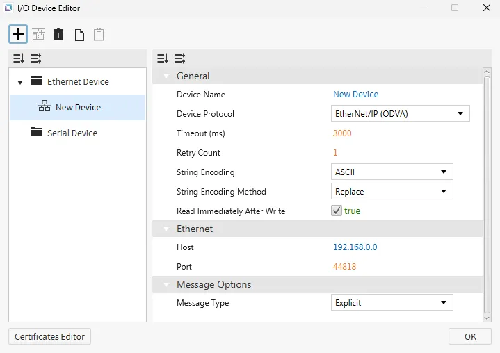
EtherNet/IP (ODVA)
EtherNet/IP (ODVA) is supported with Canvas as a way to connect with other devices that support this protocol. Users will be able to select the Message Type as explicit, implicit, or UCMM.
Explicit & UCMM Messaging
| Memory Area | Symbol | Digital | Analog | Access |
|---|---|---|---|---|
| Attribute | - | 0x{Class ID}:0x{Instance ID}.0x{Attribute ID} | 0x{Class ID}:0x{Instance ID}.0x{Attribute ID} | R/W |
| Array/Struct Attribute | - | 0x{Class ID}:0x{Instance ID}.0x{Attribute ID}[{Byte Offset}] | 0x{Class ID}:0x{Instance ID}.0x{Attribute ID}[{Bit Offset}] | R/W |
Implicit Messaging
| Memory Area | Symbol | Digital | Analog | Access |
|---|---|---|---|---|
| Input Assembly | - | input[{Byte Offset}] | input[{Bit Offset}] | R/W |
| Output Assembly | - | output[{Byte Offset}] | output[{Bit Offset}] | R/W |
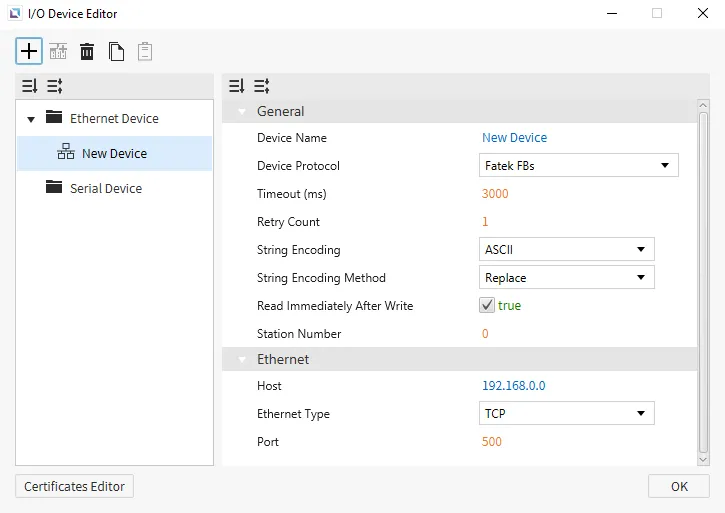
Fatek FBS
Canvas supports Fatek FBS as a way to connect with other devices that support this protocol. This protocol will work in conjunction with any Fatek PLCs. There are no specific settings that this option will bring up if selected.
Memory Area and Ranges
| Memory Area | Symbol | Bit Address | WORD Address | DWORD Address | Address Notation | Access |
|---|---|---|---|---|---|---|
| Input - Discrete | X | X0000 - X9999 | WX0000 - WX9984 | DWX0000 - DWX9968 | Decimal | R |
| Output Relay | Y | Y0000 - Y9999 | WY0000 - WY9984 | DWY0000 - DWY9968 | Decimal | R/W |
| Internal Relay | M | M0000 - M9999 | WM0000 - WM9984 | DWM0000 - DWM9968 | Decimal | R/W |
| Step Relay | S | S0000 - S9999 | WS0000 - WS9984 | DWS0000 - DWS9968 | Decimal | R/W |
| Timer - Discrete | T | T0000 - T9999 | WT0000 - WT9984 | DWT0000 - DWT9968 | Decimal | R/W |
| Counter - Discrete | C | C0000 - C9999 | WC0000 - WC9984 | DWC0000 - DWC9968 | Decimal | R/W |
| Timer Register | TMR | - | RT0000 - RT9999 | DRT0000 - DRT9998 | Decimal | R/W |
| Counter Register | CTR | - | RC0000 - RC9999 | DRC0000 - DRC9998 | Decimal | R/W |
| Data Register | HR | - | R0000 - R65535 | DR0000 - DR65534 | Decimal | R/W |
| Data Register | DR | - | D0000 - D65535 | DD0000 - DD65534 | Decimal | R/W |
| File Register | FR | - | F0000 - F65535 | DF0000 - DF65534 | Decimal | R/W |
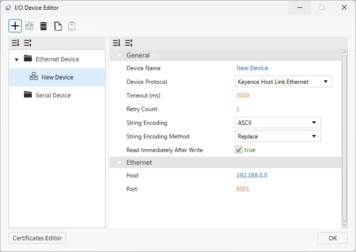
Keyence Host Link Ethernet
Canvas supports Keyence Host Link Ethernet as a way to connect with other devices that support this protocol. There are no additional configuration options.
Memory Area and Ranges
| Memory Area | Symbol | Digital | Analog | Address Notation | Access |
|---|---|---|---|---|---|
| Relay | R | R0 - R199915 | R0 - R199900 | Decimal | R/W |
| Link Relay | B | B0 - B7FFF | B0 - B7FF0 | Hexadecimal | R/W |
| Internal Auxiliary Relay | MR | MR0 - MR399915 | MR0- MR399900 | Decimal | R/W |
| Latch Relay | LR | LR0 - LR99915 | LR0 - LR99900 | Decimal | R/W |
| Control Relay | CR | CR0 - CR99915 | CR0 - CR99900 | Decimal | R/W |
| Virtual Relay | VB | VB0 - VBF9FF | VB0 - VBF9F0 | Hexadecimal | R/W |
| Data Memory | DM | - | DM0 - DM65535 | Decimal | R/W |
| Extended Data Memory | EM | - | EM0 - EM65535 | Decimal | R/W |
| File Register | FM | - | FM0 - FM524287 | Decimal | R/W |
| File Register (SQ) | ZF | - | ZF0 - ZF524287 | Decimal | R/W |
| Link Register | W | - | W0 - W7FFF | Hexadecimal | R/W |
| Temporary Data Memory | TM | - | TM0 - TM9999 | Decimal | R/W |
| Index Register | Z | - | Z1 - Z12 | Decimal | R/W |
| Timer | T | - | T0 - T9999 | Decimal | R |
| Timer (Current Value) | TC | - | TC0 - TC9999 | Decimal | R/W |
| Timer (Set Value) | TS | - | TS0 - TS9999 | Decimal | R/W |
| Counter | C | - | C0 - C9999 | Decimal | R |
| Counter (Current Value) | CC | - | CC0 - CC9999 | Decimal | R/W |
| Counter (Set Value) | CS | - | CS0 - CS9999 | Decimal | R/W |
| High-Speed Counter | CTH | - | CTH0 - CTH3 | Decimal | R/W |
| High-Speed Counter Comparator | CTC | - | CTC0 - CTC7 | Decimal | R/W |
| Control Memory | CM | - | CM0 - CM65535 | Decimal | R/W |
| Virtual Memory | VM | - | VM0 - VM65535 | Decimal | R/W |
LSIS FEnet
Canvas supports LSIS FEnet as a way to connect with other devices that support this protocol. Users can select an LSIS PLC Type within the settings to suit specific configurations.
XGI
Format
- General Format: %[Device Name][Data Type][Address Number]
-
Data TypeSymbol # of Bits BIT X 1 BYTE B 8 WORD W 16 DWORD D 32 QWORD L 64 - This is also true for I/Q and U device formats.
Address Number: denoted in the specified data type.- Example: if
Bis used,Address Number5 represents the 6th byte in the memory area (0-based index). - Example: if
Lis used,Address Number16 represents the 17th QWORD in the memory area (0-based index). - Example: the address %MB016 represents the 17th byte of the M memory area. This same starting address is pointed to using %MX128, %MW008, %MD004, or %ML002.
- Gateway will automatically convert the provided address into
BYTEnotation, unless it was specified byBITnotation. This is done to allow for continuous memory blocks to be read in a single request.
- Gateway will automatically convert the provided address into
- Example: if
-
- I/Q Device Format: %[Device Name][Data Type][Base Number].[Slot Number].[Module Number]
Base Number: Range of 0 ~ 127, represented in decimal notation.Slot Number: Range of 0 ~ 15, represented in decimal notation.Module Number: similar toAddress Numberin the generic format, where it is in the form of theData Type.
- U Device Format: %[Device Name][Data Type][Base Number].[Slot Number].[Channel Number]
Base Number: Range of 0 ~ 7, represented in decimal notation.Slot Number: Range of 0 ~ 15, represented in decimal notation.Channel Number: similar toAddress Numberin the generic format, where it is in the form of theData Type.
Memory Area and Ranges
| Device | Symbol | Bit Address | BYTE Address | WORD Address | DWORD Address | QWORD Address | Access |
|---|---|---|---|---|---|---|---|
| Input Points | I | %IX000.00.00 - %IX127.15.63 | %IB000.00.0 - %IB127.15.7 | %IW000.00.0 - %IW127.15.3 | %ID000.00.0 - %ID127.15.1 | %IL000.00.0 - %IL127.15.0 | R/W |
| Output Points | Q | %QX000.00.00 - %QX127.15.63 | %QB000.00.0 - %QB127.15.7 | %QW000.00.0 - %QW127.15.3 | %QD000.00.0 - %QD127.15.1 | %QL000.00.0 - %QL127.15.0 | R/W |
| Automatic Variable | A | %AX0000000 - %AX8388607 | %AB0000000 - %AB1048575 | %AW000000 - %AW524287 | %AD000000 - %AD262143 | %AL000000 - %AL131071 | R/W |
| Direct Variable | M | %MX0000000 - %MX4194303 | %MB000000 - %MB524287 | %MW000000 - %MW262143 | %MD000000 - %MD131071 | %ML00000 - %ML65535 | R/W |
| Direct Variable | R | %RX000000 - %RX524287 | %RB00000 - %RB65535 | %RW00000 - %RW32767 | %RD00000 - %RD16383 | %RL0000 - %RL8191 | R/W |
| Direct Variable | W | %WX0000000 - %WX8388607 | %WB0000000 - %WB1048575 | %WW000000 - %WW524287 | %WD000000 - %WD262143 | %WL000000 - %WL131071 | R/W |
| System Flag | F | %FX00000 - %FX65535 | %FB0000 - %FB8191 | %FW0000 - %FW4095 | %FD0000 - %FD2047 | %FL0000 - %FL1023 | R |
| PID Flag | K | %KX000000 - %KX134399 | %KB0000 - %KB16799 | %KW0000 - %KW8399 | %KD0000 - %KD4299 | %KL0000 - %KL2199 | R/W |
| HS Link Flag | L | %LX000000 - %LX180223 | %LB00000 - %LB22527 | %LW00000 - %LW11263 | %LD0000 - %LD5631 | %LL0000 - %LL2815 | R/W |
| Analog Refresh Flag | U | %UX0.00.000 - %UX7.15.511 | %UB0.00.00 - %UB7.15.63 | %UW0.00.00 - %UW7.15.31 | %UD0.00.00 - %UD7.15.15 | %UL0.00.00 - %UL7.15.7 | R/W |
| P2P Parameters Flag | N | %NX000000 - %NX401407 | %NB00000 - %NB50175 | %NW00000 - %NW25087 | %ND00000 - %ND12543 | %NL0000 - %NL6271 | R/W |
XGK
XGK-CPU* / XBM / XBC
Format
- General Format: [Device Name][Address Number]
- For devices that support both bit and WORD formats, the difference is the inclusion of a bit number (in Hexadecimal notation) as the last character in the address.
- If the device only supports bit addressing, then this bit number is not used (
TandCdevices).
- If the device only supports bit addressing, then this bit number is not used (
- For devices that support both bit and WORD formats, the difference is the inclusion of a bit number (in Hexadecimal notation) as the last character in the address.
- U Device Format: [Device Name][Base Number].[Slot Number].[Special Module Inner WORD Number]
Base Number: Range of 0 ~ 7, represented in decimal notation.Slot Number: Range of 0 ~ F, represented in Hexadecimal notation.Special Module Inner WORD Number: Range of 0 ~ 31, represented in decimal notation.
Memory Area and Ranges
| Device | Symbol | Bit Address | WORD Address | Access |
|---|---|---|---|---|
| Input / Output Relay | P | P00000 - P2047F | P0000 - P2047 | R/W |
| Auxiliary Relay | M | M00000 - M2047F | M0000 - M2047 | R/W |
| Keep Relay | K | K00000 - K4095F | K0000 - K4095 | R/W |
| Link Relay | L | L000000 - L11263F | L00000 - L11263 | R/W |
| Special Relay | F | F00000 - F2047F | F0000 - F2047 | R |
| Timer - Contact | T | T0000 - T2047 | - | R/W |
| Counter - Contact | C | C0000 - C2047 | - | R/W |
| Timer - Current Value | T | - | T0000 - T2047 | R/W |
| Counter - Current Value | C | - | C0000 - C2047 | R/W |
| Data Register | D | - | D00000 - D32767 | R/W |
| Special Module Register | U | - | U00.00 - U7F.31 | R/W |
| Index Register | Z | - | Z000 - Z127 | R/W |
| Communication Data Register | N | - | N00000 - N21503 | R/W |
| File Register | R | - | R00000 - R32767 | R/W |
| File Register | ZR | - | ZR00000 - ZR65535 | R/W |
XGK-CPUSN / XGK-CPUHN / XGK-CPUUN
Memory Area and Ranges
| Device | Symbol | Bit Address | WORD Address | Access |
|---|---|---|---|---|
| Input / Output Relay | P | P00000 - P4095F | P0000 - P4095 | R/W |
| Auxiliary Relay | M | M00000 - M4095F | M0000 - M4095 | R/W |
| Keep Relay | K | K00000 - K4095F | K0000 - K4095 | R/W |
| Link Relay | L | L000000 - L11263F | L00000 - L11263 | R/W |
| Special Relay | F | F00000 - F4095F | F0000 - F4095 | R |
| Timer - Contact | T | T0000 - T8191 | - | R/W |
| Counter - Contact | C | C0000 - C4095 | - | R/W |
| Timer - Current Value | T | - | T0000 - T8191 | R/W |
| Counter - Current Value | C | - | C0000 - C4095 | R/W |
| Step Controller | S | - | S000 - S255 | R/W |
| Data Register | D | - | D000000 - D524287 | R/W |
| Special Module Register | U | - | U00.00 - U7F.31 | R/W |
| Index Register | Z | - | Z000 - Z255 | R/W |
| Communication Data Register | N | - | N00000 - N21503 | R/W |
| File Register | R | - | R00000 - R32767 | R/W |
| File Register | ZR | - | ZR000000 - ZR524287 | R/W |
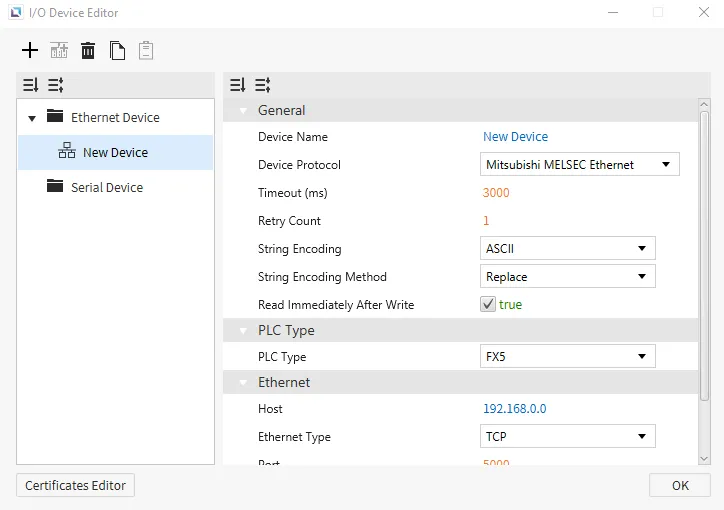
Mitsubishi MELSEC Ethernet
Canvas supports Mitsubishi MELSEC Ethernet as a way to connect with other devices that support this protocol. Users can select a Mitsubishi PLC Type within the settings to suit specific configurations better. Users will also be able to choose a Frame Type.
Memory Area and Ranges
| Memory Area | Symbol | Digital | Analog | Address Notation | Access |
|---|---|---|---|---|---|
| Input | X | X0000 - X1757 | - | Octal | R |
| Output | Y | Y0000 - Y1757 | - | Octal | R |
| Internal Relay | M | M0000 - M7659 | - | Decimal | R/W |
| Latching Relay | L | L0000 - L7659 | - | Decimal | R/W |
| Annunciator | F | F000 - F107 | - | Decimal | R/W |
| Edge Relay | V | V0000 - V2029 | - | Decimal | R/W No iQ-F No FX5 |
| Link Relay | B | B000 B0EF | - | Hexadecimal | R/W |
| Step Relay | S | S0000 - S4079 | - | Decimal | R/W |
| Timer - Contact | TS | TS000 - TS496 | - | Decimal | R/W |
| Timer - Coil | TC | TC000 - TC496 | - | Decimal | R/W |
| Retentive Timer - Contact | SS | SS00 - SS00 | - | Decimal | R/W |
| Retentive Timer - Coil | SC | SC00 - SC00 | - | Decimal | R/W |
| Counter - Contact | CS | CS000 - CS240 | - | Decimal | R/W |
| Counter - Coil | CC | CC000 - CC240 | - | Decimal | R/W |
| Link Special Relay | SB | SB000 - SB1EF | - | Hexadecimal | R/W |
| Special Relay | SM | SM0000 - SM9979 | - | Decimal | R/W |
| Data Register | D | - | D0000 - D7999 | Decimal | R/W |
| Link Register | W | - | W000 - W1FF | Hexadecimal | R/W |
| Timer - Current Value | TN | - | TN000 - TN511 | Decimal | R/W |
| Retentive Timer - Current Value | SN | - | SN00 - SN15 | Decimal | R/W |
| Counter - Current Value | CN | - | CN000 - CN255 | Decimal | R/W |
| Link Special Register | SW | - | SW000 - SW1FF | Hexadecimal | R/W |
| Special Register | SD | - | SD00000- SD11999 | Decimal | R/W |
Modbus TCP
Canvas supports Modbus TCP as a way to connect with other devices that support this protocol. Users can use Swap 16 on Integers, Strings, Float32, and Float64, Swap 32 on Integers, Float32, and Float64 or Swap 64 on Integers, Float32, and Float64. Users will also have to set the Unit Identifier for Modbus TCP to correctly identify the device to communicate with.
Format
- General Format: {Memory Area Symbol}{Address Number}
Memory Area Symbol: refer to the table below. This component is required.- For Coil memory areas,
Memory Area Symbol0, the leading 0 cannot be dropped.
- For Coil memory areas,
Address Number: index of the memory area to access, represented in decimal notation.- Leading zeros are not required (i.e., 00025 is equivalent to 25).
Memory Area and Ranges
| Memory Area | Symbol | Digital Tag | Analog Tag | Access |
|---|---|---|---|---|
| Coil | 0 | 000001 - 029999 | - | R/W |
| Input | 1 | 100001 - 129999 | - | R |
| Input Register | 3 | - | 300001 - 329999 | R |
| Holding Register | 4 | - | 400001 - 429999 | R/W |
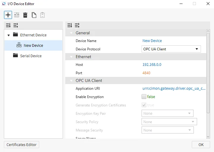
OPC UA Client
Canvas supports OPC UA Client as a way to connect to other devices that support this protocol. Users can Enable Encryption and enhance security for their OPC UA Client. Users can also manage specific Security Policies and change the authentication method.
Format
Tags on the OPC UA Server are assigned a unique NodeId for identification, which is what is used in a tag's address. The OPC UA NodeId is comprised of three components: namespaceIndex, identifierType, and identifier. The components can be serialized into a string using the following format:
ns={namespaceIndex};{identifierTypeFlag}={identifier}
The nameSpaceIndex represents the namespace which the Node belongs to. This namespace will have a qualified string name, but it will be registered on the OPC UA Server and assigned an index, which is what it is referred by.
The identifierType denotes the data type in which the identifier is represented. There are four types: NUMERIC, STRING, GUID, and OPAQUE.
identifierType | identifierTypeFlag | identifier Data Type |
|---|---|---|
| NUMERIC | i | Unsigned Integer |
| STRING | s | String |
| GUID | g | Guid |
| OPAQUE | b | ByteString |
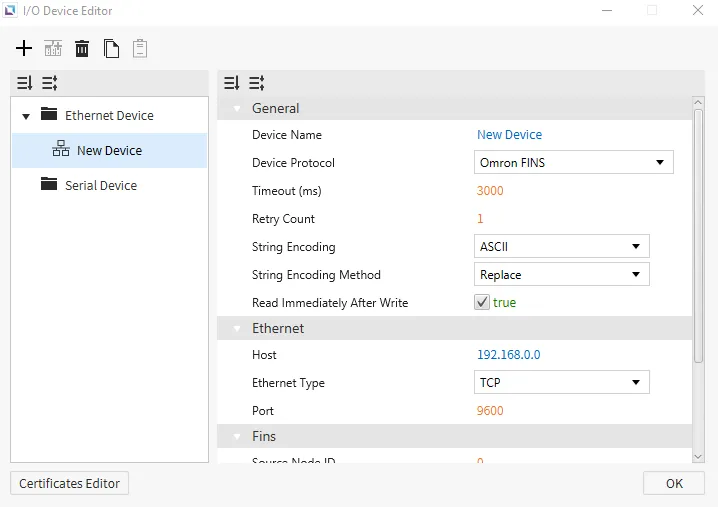
Omron FINS
Canvas supports Omron FINS as a way to connect to other devices that support this protocol. Users will need to set up Fins to use it. Users must specify the ID of the Source Node, Source Network, Destination Network, Destination Node, and Destination Unit to have Omron FINS set up correctly.
- General Format: {Symbol}{Starting Address}
Symbol: refer to the tables below.- This driver uses some non-standard symbols for the
CounterandTimermemory areas.
- This driver uses some non-standard symbols for the
Starting Address: represented in decimal notation. Does not use leading zeros.
- Expansion Data Notation: E{Bank Number}_{Starting Address}
Bank Number: represented in Hexadecimal notation.- Example: WORD-based tag with
Starting Address149 onBank11 (0xB): EB_00149.
- Example: WORD-based tag with
Starting Address: represented in decimal notation. Does not use leading zeros.
CS1 & CJ1
Memory Area and Ranges
| Memory Area | Symbol | Bit Address | WORD Address | Access |
|---|---|---|---|---|
| Auxiliary Relay | A | A000.00 - A447.15 | A000 - A447 | R |
| A448.00 - A959.15 | A448 - A959 | R/W | ||
| Common I/O | CIO | CIO0000.00 - CIO6143.15 | CIO0000 - CIO6143 | R/W |
| Counter Preset Value | CV | - | CV0000 - CV4095 | R/W |
| Counter Status | CC | CC0000 - CC4095 | - | R/W |
| Data Memory | D | D00000.00 - D32767.15 | D00000 - D32767 | R/W |
| Expansion Data Memory | E | E0_00000.00 - EC_32767.15 | E0_00000 - EC_32767 | R/W |
| Holding Relay | H | H0000.00 - H1535.15 | H0000 - H1535 | R/W |
| Index Register | IR | - | IR00 - IR15 | R/W |
| Timer Preset Value | TV | - | TV0000 - TV4095 | R/W |
| Timer Status | TC | TC0000 - TC4095 | - | R/W |
| Working Relay | W | W000.00 - W511.15 | W000 - W511 | R/W |
CJ2
Memory Area and Ranges
| Memory Area | Symbol | Bit Address | WORD Address | Access |
|---|---|---|---|---|
| Auxiliary Relay | A | A000.00 - A447.15 | A000 - A447 | R |
| A0448.00 - A1471.15 | A0448 - A1471 | R/W | ||
| A10000.00 - A11535.15 | A10000 - A11535 | R | ||
| Common I/O | CIO | CIO0000.00 - CIO6143.15 | CIO0000 - CIO6143 | R/W |
| Counter Preset Value | CV | - | CV0000 - CV4095 | R/W |
| Counter Status | CC | CC0000 - CC4095 | - | R/W |
| Data Memory | D | D00000.00 - D32767.15 | D00000 - D32767 | R/W |
| Expansion Data Memory | E | E0_00000.00 - EF_32767.15 | E0_00000 - EF_32767 | R/W |
| Holding Relay | H | H0000.00 - H1535.15 | H0000 - H1535 | R/W |
| Index Register | IR | - | IR00 - IR15 | R/W |
| Timer Preset Value | TV | - | TV0000 - TV4095 | R/W |
| Timer Status | TC | TC0000 - TC4095 | - | R/W |
| Working Relay | W | W000.00 - W511.15 | W000 - W511 | R/W |
Proface GPEthernet
Canvas supports Proface GPEthernet as a way to connect to devices that support this protocol. Users can use Swap 16 on Integers and Strings or Swap 32 on Integers.
Memory Area and Ranges
| Memory Area | Analog | Address Notation | Access |
|---|---|---|---|
| System Data | 0000 - 0019 | Decimal | R/W |
| User | 0020 - 2031 | Decimal | R/W |
| Special Relay | 2032 - 2047 | Decimal | R/W |
| User | 2096 - 8899 | Decimal | R/W |
| 9000 Area | 9000 - 9999 | Decimal | R/W |
Siemens S7
Canvas supports Siemens S7 as a way to connect to devices that support this protocol. Users can set up the Slot Number and Rack Number of the S7. This will need to be correct to grab information from the correct device.
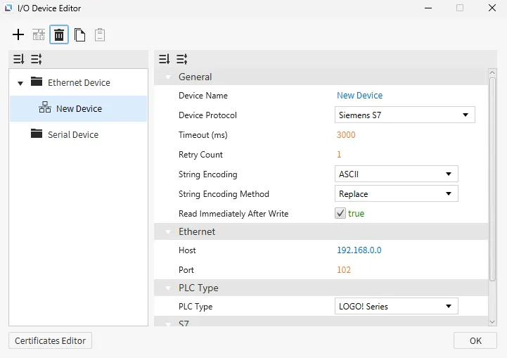
LOGO! 0BAx Series
Memory Area and Ranges
| Memory Area | Symbol | Digital | Analog | Address Number System | Access |
|---|---|---|---|---|---|
| Process Inputs | I | I1 - I64 | - | Decimal | R |
| Process Outputs | Q | Q1 - Q64 | - | Decimal | R/W |
| Markers | M | M1 - M112 | - | Decimal | R/W |
| Variables | V | V0.0 - V14697.7 | V0 - V14697 | Decimal | R/W |
| Analog Inputs | AI | AI1.0 - AI16.15 | AI1 - AI16 | Decimal | R |
| Analog Outputs | AQ | AQ1.0 - AQ16.15 | AQ1 - AQ16 | Decimal | R/W |
| Analog Makers | AM | AM1.0 - AM64.15 | AM1 - AM64 | Decimal | R/W |
| Function | F | F1 - F4 | - | Decimal | R/W |
| Cursor | C | C1 - C4 | - | Decimal | R/W |
S7 Series
Memory Area and Ranges
| Memory Area | Symbol | Digital | Analog | Address Number System | Access | Note |
|---|---|---|---|---|---|---|
| Process Inputs | I | I0.0 - I1023.7 (Max 65535.7) | I0 - I1023 (Max 65535) | Decimal | R | - |
| Process Outputs | Q | Q0.0 - Q1023.7 (Max 65535.7) | Q0 - Q1023 (Max 65535) | Decimal | R/W | - |
| Markers | M | M0.0 - M4095.7 (Max 65535.7) | M0 - M4095 (Max 65535) | Decimal | R/W | - |
| DB | DB | DB0,0.0 - DB65535,65535.7 | DB0,0 - DB65535,65535 | Decimal | R/W | Range varies depending on PLC program |
| Counters | C | - | C0 - C65535 | Decimal | R/W | - |
| Timer | T | - | T0 - T65535 | Decimal | R/W | - |
Notes
- S7 1200/1500 notes:
- Only global DBs can be accessed.
- To access a DB memory area in S7 1200/1500, some additional settings in PLC software (TIA Portal) are required.
- The optimized block access must be turned off.
- Select the DB in the left pane under “Program blocks” and press [Alt+Enter]. (Or in the contextual menu, select “Properties…”)
- Uncheck Optimized block access
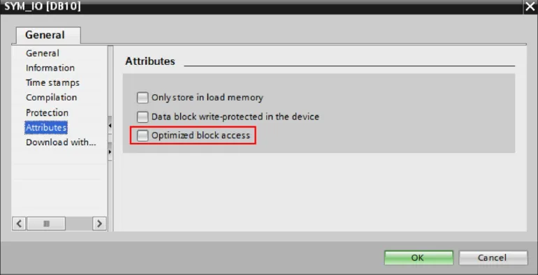
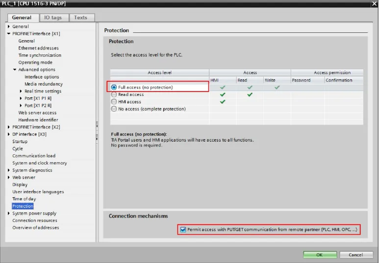
- The access level must be “full,” and the “connection mechanism” must allow GET/PUT.
- Select the CPU project in the left pane and press [Alt+Enter]. (Or in the contextual menu, select “Properties…”.)
- Select “Full access” and check “Permit access with PUT/GET …” as in the image below.