Tag Editor Exercise
Exercise
Exercise: Demonstrating the use of the Tag Editor
Please follow the below exercise to understand Tag Editor functionality.
Configuration
The following configuration is used to set up this exercise.
Tag Configuration
-
Open the tag editor by clicking the Open Tag Editor icon in the Tag List tab or navigate to Tools > Tag Editor.
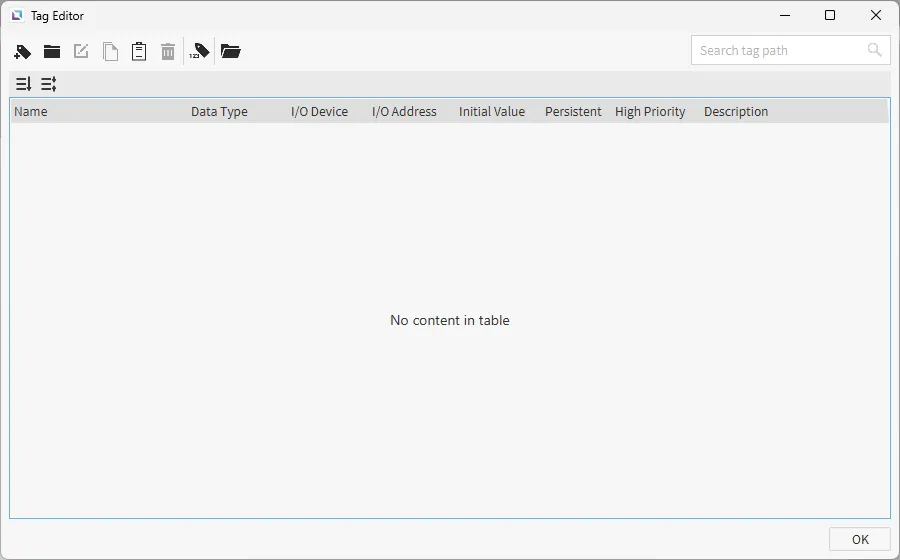
- Click the Add Tag icon or right-click and select New Tag, and create the following tags:
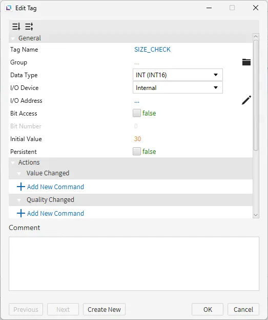
- Size_check
- Data type: INT (INT16)
- I/O Device: Internal
- I/O Address: ...
- Initial value: 30
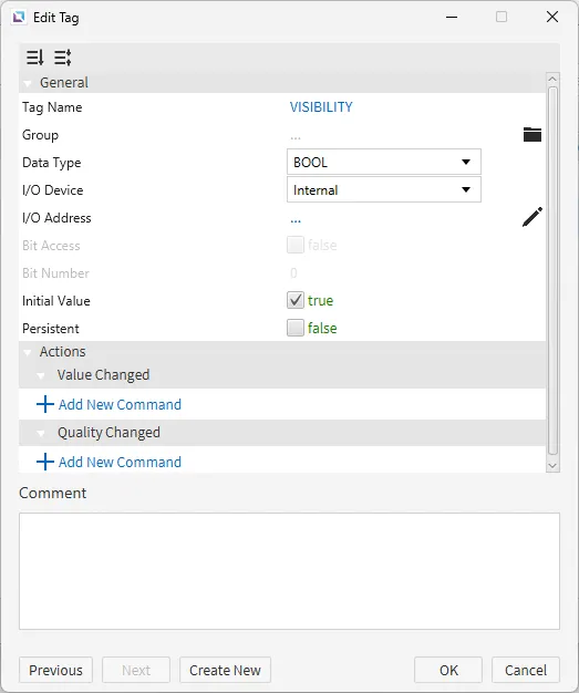
- VISIBILITY
- Data type: BOOL
- I/O Device: Internal
- I/O Address: ...
- Initial value: true
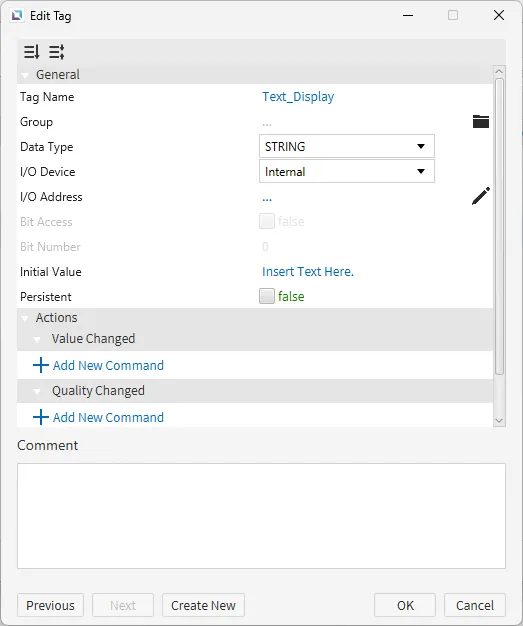
- Text_Display
- Data type: STRING
- I/O Device: Internal
- I/O Address: ...
- Initial value: Insert Text Here.
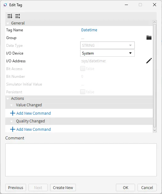
- Text_Display
- I/O Device: System
- I/O Address: :sys /datetime:
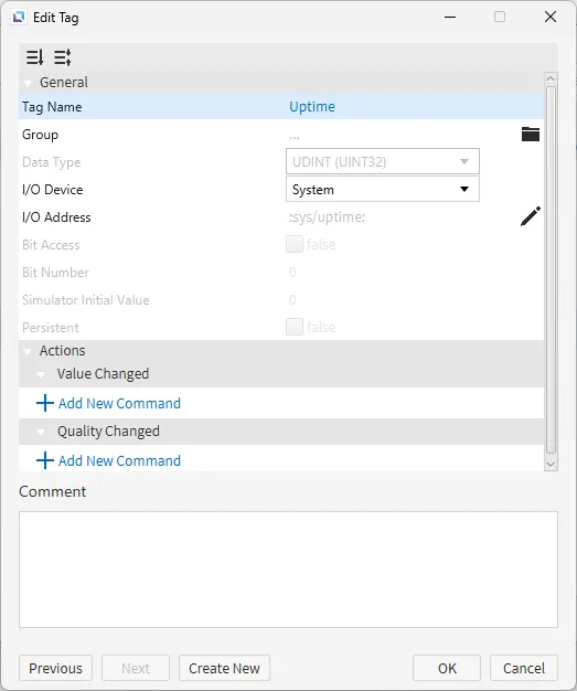
- Uptime
- I/O Device: System
- I/O Address: :sys /uptime:
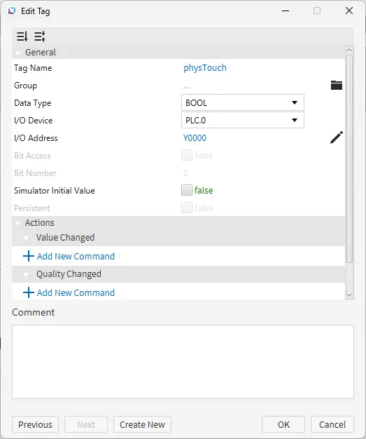
- physTouch
- Data type: BOOL
- I/O Device: PLC.0 (name of I/O device created with the I/O Device Editor)
- I/O Address: Y0000 (address of I/O device)
- Size_check
- Click the Add Tag icon or right-click and select New Tag, and create the following tags:
Project Configuration
-
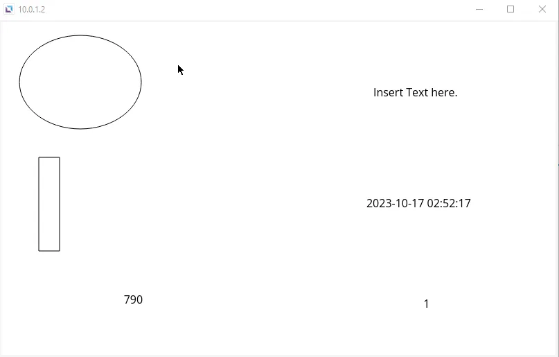
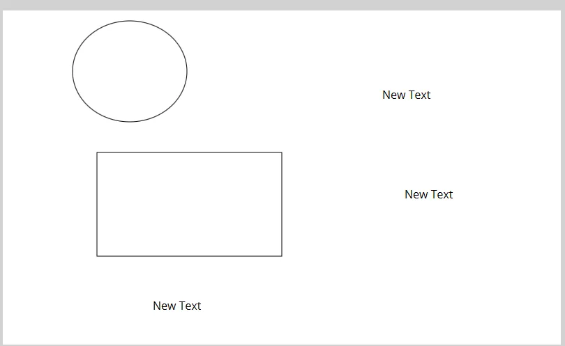
Click on the Insert Rectangle or go to Insert > Rectangle to begin drawing it.
Then, create four text displays, click Insert Text, or go to Insert > Text.
Last, create an ellipse. Click Insert Ellipse in the toolbar, or go to Insert > Ellipse.
-
Connect the following tags to the corresponding objects.
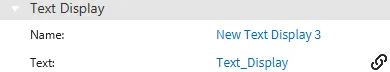
First, for the text display, drag-and-drop the Text_Display tag onto it. This will bind the tag value into the text display's value property.
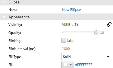
Next, select the ellipse. Drag-and-drop the VISIBILITY tag onto the visibility property under Appearance. Or, hover over the visibility property and select the chain link icon. Bind the VISIBILITY tag manually.
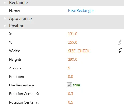
Click the rectangle and navigate to the Position properties. Drag-and-drop the Size_Check tag to the width property.
For each of the remaining text displays, drag-and-drop the Datetime, Uptime, and physTouch tags onto them. Each text display's value property will be bound to the tag that was bound to it.
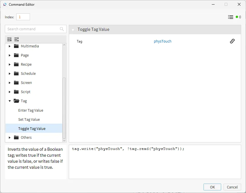
Lastly, click on the text display with the physTouch tag bound to it. Under the Actions properties, select On Press and click Add New Command. Select the Toggle Tag Value command and bind the physTouch tag to it.
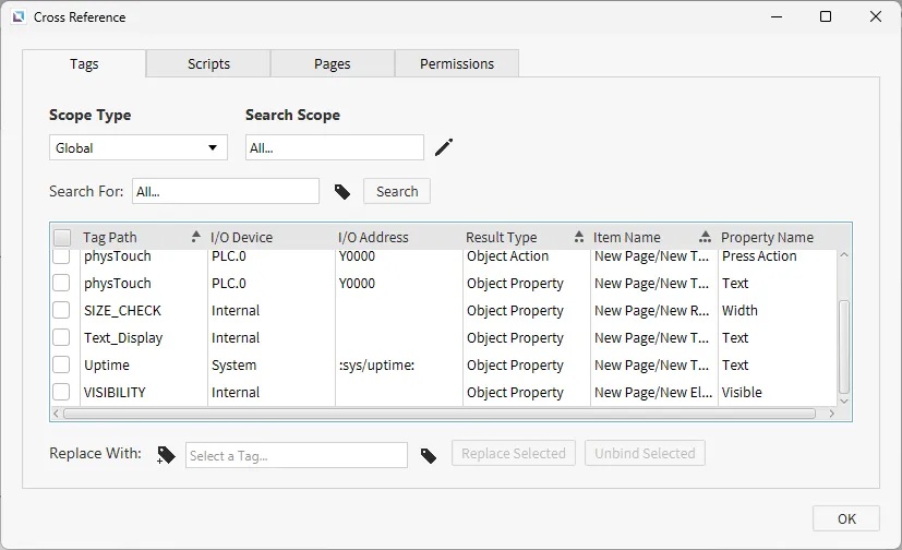
Cross Reference Configuration
- Press F3 on the keyboard or go to Tools > Cross Reference to ensure each tag is properly bound. This will display the current tags bound to the project and the property they are attached to.
Project Deployment
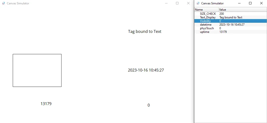
- Click Tools > Launch Simulator to launch the Canvas Simulator.
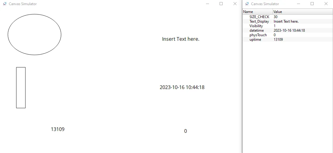
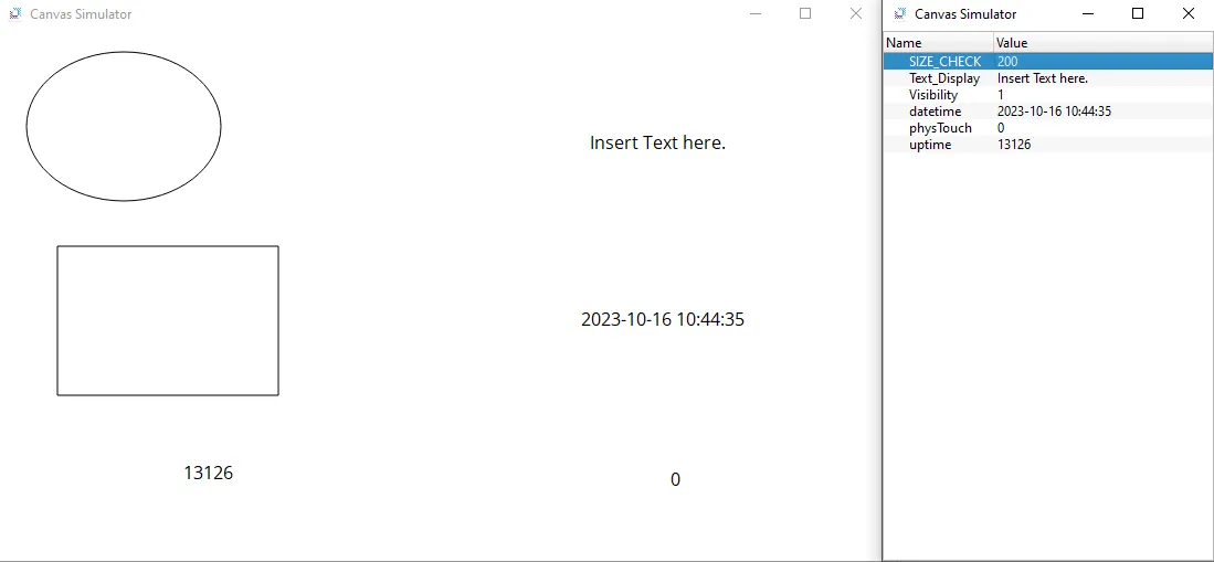
- Change the value of the Size_Check tag from 30 to 200. The width of the rectangle should now change. This will indicate that the tag was correctly bound.
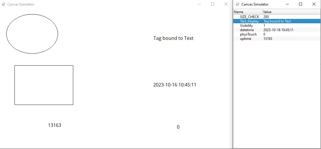
- Change the value of the Text_Display tag to “Tag bound to Text.” The text in the box should also change to indicate that the tag was bound correctly.
- Now, change the VISIBILITY tag to 0 (false). This should hide the ellipse and will indicate that the tag is bound to the visibility property.
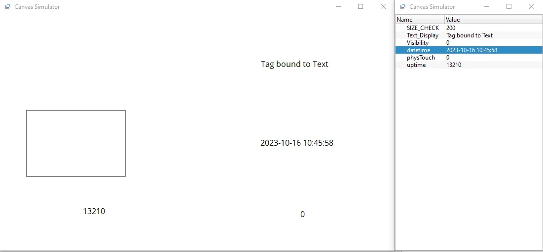
- Now, try to change the Datetime tag to any number. Due to it being read directly from the system, no manual value changes can be made.
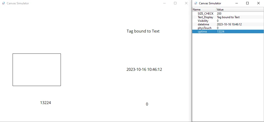
- Attempt the above step with the Uptime tag, and similar to the Datetime tag, due to it being read directly from the system, no manual value changes can be made.
- Under Tools > Connection Setup, select the HMI to download this project to. Select Download (PC → HMI). Wait for it to finish uploading to the HMI. Once it is finished downloading, it should open on the HMI. Touch the text that is connected to the physical device. The number should change from 0 to 1. This indicates that the device is communicating with the PLC properly.